The space coordinate system that we choose is somewhat arbitrary, perhaps we may choose orthogonal (mutually perpendicular) x,y and z coordinates that align with the surface of the earth where we happen to be, or we could choose any other convenient alignment. In the same way the origin point of the coordinate system is similarly arbitrary.
This can be useful as changing the frame of reference (different observers) in an appropriate way could simplify the mathematics.
When we go on to look at dynamics we shall see that the laws of motion are independent of certain changes in the coordinate system such as:
- time shift
- space translation
- space rotation
- uniform linear velocity
We can think of these as symmetries.
This means that if we do a mechanics experiment where the frame of reference is transformed in any of these ways then we will get the same result (provided that we are consistent: if we are using some equation then all the quantities in that equation must be measured in the same coordinate system). in fact this can be stated in a stronger way: there is no way, by doing physics experiments that we can determine an absolute time, space or velocity, these things always have to be measured relative to something. This relativity principle applies both to Newtonian and Einsteinian physics although, as we will see below, the nature of the velocity transform depends on which of these we are using.
There may be other symmetries, for instance, reflection in space or time, however there are some frames of reference which will alter the laws of physics, for example, where the frame of reference is accelerating or in a constant angular velocity.
We will now look at these changes or transforms individually in more detail.
Time Shift Transform
We can change the frame of reference by shifting the timeframe as follows:
t'=t - t0
where:
- t' = time in new frame of reference (scalar value)
- t0 = time in new frame of reference when t=0 (scalar value)
- t = time in original frame of reference (scalar value)
Alternatively we could use t'=t + t0 if we defined t0 as time in original frame of reference when t'=0
Another way to express this is to represent space-time as a 4 dimensional vector in which case, for newtonian physics, we get:
Time is not absolute in either Newtonian or Einsteinian physics in the sense that there is no preferred origin (except perhaps the time of the big bang?) but in Einsteinian physics time is even less absolute in that time intervals change due to relative velocity.
Space Translation Transform
We can change the frame of reference by shifting the origin as follows:
x'=x - x0
where:
- x' = position in new frame of reference (vector value)
- x0 = position in new frame of reference when x=0 (vector value)
- x = position in original frame of reference (vector value)
Alternatively we could use x'=x + x 0 if we defined x 0 as time in original frame of reference when x'=0
Another way to express this is to represent space-time as a 4 dimensional vector in which case, for newtonian physics, we get:
Position is not absolute in either Newtonian or Einsteinian physics in the sense that there is no preferred origin but in Einsteinian physics distance is even less absolute in that distances change due to relative velocity.
Space Rotation Transform
In the same way we can rotate the space frame as follows:
|
= |
| 1 |
0 |
0 |
0 |
| 0 |
rxx |
rxy |
rxz |
| 0 |
ryx |
ryy |
ryz |
| 0 |
rzx |
rzy |
rzz |
|
|
Uniform Linear Velocity Transform
The transform between moving frames depends on whether we are using Newtonian or Einsteinian physics in Newtonian physics we use the Galilean transform and in Einsteinian physics we use the Lorentz transform.
Galilean transform
Assuming the relative motion 'v' is along the x dimension then x -> x0 + vxt
or if we have components of velocity in all dimensions the transform will be:
|
= |
| 1 |
0 |
0 |
0 |
| vx |
1 |
0 |
0 |
| vy |
0 |
1 |
0 |
| vz |
0 |
0 |
1 |
|
|
where:
- vx,vy,vz= relative velocity of the two reference frames in x,y and z directions.
- x,y,z= position in original frame.
- x',y',z'= position in transformed frame.
in other words point:
|
is transformed to: |
| t |
| x + vxt |
| y + vyt |
| z + vzt |
|
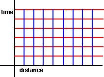
The nature of this transform is a shear (also known as skew) transform:
 |
—» |
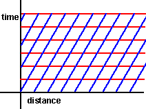 |
When doing this we choose to make time 'absolute' in that the time lines are left horizontal wheras the position lines are skewed althogh I guess that this is just a covention and we could have skewed the time and made the distance absolute.
more about Galilean transform.
Practical Issues
At first, it may seem a bit academic to transform these quantities into different
frames-of-reference but, this is important for solving practical problems like
collisions. For instance, the two objects colliding will have their inertial
tensors defined in their own local coordinates, but when we work out the collision
response, the impulse will have to be calculated in some common coordinate system.
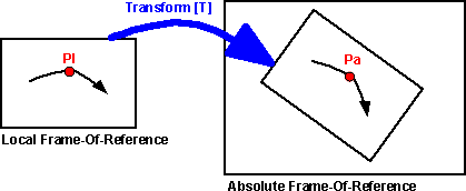
What we are doing here is observing the same particle or solid object from
different frames-of-reference. When the frames-of-reference are static (not
moving relative to each other). Then the Newtonian laws will apply, regardless
of where, or which direction, that we are looking at them from, provided that
we are consistent about measuring all quantities on the same frame-of-reference.
It may be that the transform is changing with time, for example, if we are
trying to solve a collision response, we might want to work in the frame-of-reference
of one of the objects that is colliding. This object may be moving, so its frame-of-reference
is moving with respect to the absolute coordinate system.
Do all the laws of physics apply when observing them from a moving frame-of-reference?
If the frame-of-reference is moving with a constant linear velocity, then the
Newtonian laws will apply just the same. A stationery object in one frame-of-reference
may appear to be moving in another, but provided that we are constant about
which frame-of-reference that we are working in, neither will contravene the
laws. (Einsteins laws may not apply, the speed of light is the same in each
frame-of-reference, relativity is not relative to the frame-of-reference - we
are interested in slow speed interactions so this is not an issue for us).
However, if the frame-of-reference has angular motion (even if its constant),
or if the frame-of-reference is accelerating, or if it has some irregular motion,
then the Newtonian laws will not apply in this frame-of-reference.
To take an example, imagine a solid object travailing in free space, it may
be spinning and have linear velocity as well. We may want to work in this objects
own coordinate system, because this frame-of-reference is rotating, the Newtonian
laws may not apply, for example an object which is stationary in the absolute
frame-of-reference will appear to be traveling in a spiral in this objects frame
of reference. An object with no forces acting on it should not be moving in
a spiral, so Newtonian laws do not apply in this frame-of-reference. However,
if we want to apply this inertia tensor, then we have to work in the local coordinate
system of the rotating object.
|
|
= |
| ixx |
ixy |
ixz |
| iyx |
iyy |
iyz |
| izx |
izy |
izz |
|
|
So, we have to be careful. When we are calculating torques and forces, we often
want to work in its local coordinate system, but when we are calculating motion
we probably want to work in absolute coordinates.
Using matrix algebra to calculate transforms to other frames-of-reference
As described here, a
4x4 matrix can be used to represent a rotation and a translation in 3 dimensions.
So we can use matrix algebra to translate from one frame of reference to another.
The transform will take a 3d vector representing a point in absolute coordinates
and convert it into a 3d vector representing a point in absolute coordinates:
 a
= [T]
 l
l
It is possible to have many layers of one frames-of-reference inside another.
For example, if we know the position of the moon relative to the earth [Tme]
and we know the position of the earth in the frame-of-reference of the sun [Tes],
then we could work out the position of a point on the moon in the frame of reference
of the sun [Tms].
It turns out that transforms can be concatenated by multiplying
their corresponding matrices. So [Tms] = [Tes]*[Tme].
One way to represent this is to use a scene graph. We could use a scene graph
is a similar way to VRML. We could put dynamics information into the scene graph
in the same way that shape information is. In this page I would like to work
out the effect of transforming dynamics information in this way.
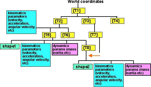
The transform allows us to plug in a coordinate in the local frame-of-reference
and get the coresponding coordinate in the absolute frame-of-reference.
|
|
= |
| rxx |
rxy |
rxz |
tx |
| ryx |
ryy |
ryz |
ty |
| rzx |
rzy |
rzz |
tz |
| 0 |
0 |
0 |
1 |
|
|
= |
| Plx * rxx + Ply * rxy
+ Plz * rxz + tx |
| Plx * ryx + Ply * ryy
+ Plz * ryz + ty |
| Plx * rzx + Ply * rzy
+ Plz * rzz + tz |
| 1 |
|
For Solid objects, we need to specify both the location and the orientation
of the object to define its position. So for solid objects we can easily translate
its centre-of-mass (c-of-m) in this way, but how do we translate its orientation?
One way that occurred to me would be to, take a point an infinitesimal distance
away from from the c-of-m, translate that, and then see the orientation of this
point relative to the translated c-of-m.
|
|
= |
| rxx |
rxy |
rxz |
tx |
| ryx |
ryy |
ryz |
ty |
| izx |
izy |
izz |
tz |
| 0 |
0 |
0 |
1 |
|
| Plx + dPlx |
| Ply + dPly |
| Plz + dPlz |
| 1 |
|
= |
| (Plx + dPlx) * rxx + (Ply
+ dPly) * rxy + (Plz + dPlz)
* rxz + tx |
| (Plx + dPlx) * ryx + (Ply
+ dPly) * ryy + (Plz + dPlz)
* ryz + ty |
| (Plx + dPlx) * rzx + (Ply
+ dPly) * rzy + (Plz + dPlz)
* rzz + tz |
| 1 |
|
So the relative position is given by:
|
|
= |
|
- |
|
= |
| dPlx * rxx + dPly * rxy
+ dPlz * rxz |
| dPlx * ryx + dPly * ryy
+ dPlz * ryz |
| dPlx * rzx + dPly * rzy
+ dPlz * rzz |
| 1 |
|
= |
| rxx |
rxy |
rxz |
0 |
| ryx |
ryy |
ryz |
0 |
| izx |
izy |
izz |
0 |
| 0 |
0 |
0 |
1 |
|
|
So to transform a movement, then we transform it by the rotational part of
the transform without the translational part of the matrix. Alternatively, if
we don't want to modify the transform matrix, we could just use 0 for the 4th
row of a relative movement vector, then the translational part will automatically
be ignored.
But if we measuring orientation with 3 angles, θx,
θy and θz.
How can we translate this with [T]? This may seem a bit stange as we are using
[T] to define the rotation of the frame-of-reference and θx,
θy and θz
to define the orientation in each frame-of-reference. The advantage of using
θx, θy
and θz would be that this notation
would fit in better with the physics equations.
Using 6 dimensional vectors to calculate transforms to other frames of reference
For Solid objects, we need to specify both the location and the orientation
of the object to define its position. It might be useful if we could represent
the transform of both location and orientation in one equation. To do this we
need a 6x6 matrix as the position has 6 degrees of freedom.
I am not sure if this will work for position because the normal rules of algebra
don't apply when combining rotations (see
rotations). Can anyone help me prove if this will work?
|
|
= |
| m00 |
m01 |
m02 |
m03 |
m04 |
m05 |
| m10 |
m11 |
m12 |
m13 |
m14 |
m15 |
| m20 |
m21 |
m22 |
m23 |
m24 |
m25 |
| m30 |
m31 |
m32 |
m33 |
m34 |
m35 |
| m40 |
m41 |
m42 |
m43 |
m44 |
m45 |
| m50 |
m51 |
m52 |
m53 |
m54 |
m55 |
|
|
However I am sure it would work for velocities because infinitesimally small
rotations can be combined in the usual way.
|
|
= |
| m00 |
m01 |
m02 |
m03 |
m04 |
m05 |
| m10 |
m11 |
m12 |
m13 |
m14 |
m15 |
| m20 |
m21 |
m22 |
m23 |
m24 |
m25 |
| m30 |
m31 |
m32 |
m33 |
m34 |
m35 |
| m40 |
m41 |
m42 |
m43 |
m44 |
m45 |
| m50 |
m51 |
m52 |
m53 |
m54 |
m55 |
|
|
This 6x6 matrix does not contain any extra information than the 4x4 transform
[T] (even the 4x4 transform has redundant information when we are considering
only a rotation and translation).
However, multiplication of a 6d vector by a 6x6 matrix, might be a lot easier
than multiPlying 4x4 matrix by a 4x4 matrix (which we would have
to do several times if we are going to represent rotations by using matrices).
The advantage of this notation is that:
- The linear and angular quantities are dealt with is the same equation.
- The angular velocities and accelerations are defined in a way that is consistent
with the usual dynamics equations.
Issues:
- Not sure if we can use this to transform points.
- Not sure how we would concatinate transforms (transform within a transform).
Point ( )
)
Every coordinate point in the local frame of reference can be transformed to
a coordinate in the absolute frame of reference  a
= [T]
  l
. This can be thought of as the same point just measured in a different coordinate
reference. A solid object can be transformed in this way by seperately transforming
each point that makes it up.
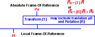
This transform [T] is a 4x4 matrix and is capable of representing lots of tranforms
such as sheer, scaleing, reflection, etc. which are not valid operations for
a solid body, also it is very wasteful using a 4x4 matrix. Since we only want
to represent translations and rotations, it may be more efficient to represent
it in terms of a 3x3 rotation matrix [R] and a translation  0.
0.
 a
= [R]
  l
+
l
+  0
0
Where:
 a
is the position in absolute coordinates.
a
is the position in absolute coordinates.- [R] is a 3x3 rotational matrix
-
 l
is the position in local coordinates.
 0
is the linear translation.
But we still have the problem that [R] could be used to repesent invalid operations
for a solid object, we need to ensure that [R] is orthogonal. The problem is
that if a calculation involves lots of transforms then rounding errors could
distort [R], therefore we need to normalise (or should that be orthogonalise)
after tranforms are combined.
One way round this would be to work from the quaternion
[Q] to represent the rotation, as the quaternion is easier to normalise:
 a
= a
= |
| 1 - 2 * ( yy + zz ) |
2 * ( xy - zw ) |
2 * ( xz + yw ) |
| 2 * ( xy + zw ) |
1 - 2 * ( xx + zz ) |
2 * ( yz - xw ) |
| 2 * ( xz - yw ) |
2 * ( yz + xw ) |
1 - 2 * ( xx + yy ) |
|
 l
+ l
+  0 0 |
where:
- xx = qx* qx
- xy = qx * qy
- xz = qx * qz
- xw = qx * qw
- yy = qy * qy
- yz = qy * qz
- yw = qy * qw
- zz = qz * qz
- zw = qz * qw
- qx, qy, qz and qw are the values of the quaternion.
Linear Velocity( )
)
 a
= d
a
= d a
/ dt = d[T]
  l
/dT
l
/dT
 a
= d a
= d a
/ dt = d a
/ dt = d |
| rxx * Plx + rxy * Ply
+ rxz * Plz + tx |
| ryx * Plx + ryy * Ply
+ ryz * Plz + ty |
| rzx * Plx + rzy * Ply
+ rzz * Plz + tz |
| 0 |
|
/dt |
using partial differential equations:
d (u * v) / dt = u dv/dt + v du/dt
so,
 a
= a
= |
| rxx * d Plx/dt + d rxx/dt
* Plx + rxy * d Ply/dt + d rxy/dt
* Ply + rxz * d Plz/dt +d rxz/dt
* Plz + d tx/dt |
| ryx * d Plx/dt + d ryx/dt
* Plx + ryy * d Ply/dt + d ryy/dt
* Ply + ryz * d Plz/dt + d ryz/dt
* Plz + d ty/dt |
| rzx * d Plx/dt + d rzx/dt
* Plx + rzy * d Ply/dt + d rzy/dt
* Ply + rzz * d Plz/dt + d rzz/dt
* Plz + d tz/dt |
| 0 |
|
 a
= a
= |
| rxx * d Plx/dt + rxy
* d Ply/dt + rxz * d Plz/dt |
| ryx * d Plx/dt + ryy
* d Ply/dt + ryz * d Plz/dt |
| rzx * d Plx/dt + rzy
* d Ply/dt + rzz * d Plz/dt |
| 0 |
|
+ |
| d rxx/dt * Plx + d rxy/dt
* Ply + d rxz/dt * Plz |
| d ryx/dt * Plx + d ryy/dt
* Ply + d ryz/dt * Plz |
| d rzx/dt * Plx + d rzy/dt
* Ply + d rzz/dt * Plz |
| 0 |
|
+ |
| d tx/dt |
| d ty/dt |
| d tz/dt |
| 0 |
|
therefore:
 a
= [T1]
 l
+ [T2]
 l
+
l
+  r
r
where:
 a
= linear velocity of point in absolute coordinates
 l
= linear velocity of point in local coordinates
 r
= linear velocity of local coordinates relative to absolute coordinates
r
= linear velocity of local coordinates relative to absolute coordinates- [T1] = transform [T] with only rotational components (m03 = m02
= m01 =0)
- [T2] = rate of change of rotational components of [T]
-
| d rxx / dt |
d rxy / dt |
d rxz / dt |
d tx / dt |
| d ryx / dt |
d ryy / dt |
d ryz / dt |
d ty / dt |
| d izx / dt |
d izy / dt |
d izz / dt |
d tz / dt |
| 0 |
0 |
0 |
1 |
|
If the local coordinates are not rotated then:
 a
= a
=  l
+ l
+ r r
| [T1]= |
| 1 |
0 |
0 |
0 |
| 0 |
1 |
0 |
0 |
| 0 |
0 |
1 |
0 |
| 0 |
0 |
0 |
1 |
|
| [T2]= |
| 0 |
0 |
0 |
0 |
| 0 |
0 |
0 |
0 |
| 0 |
0 |
0 |
0 |
| 0 |
0 |
0 |
0 |
|
|
Angular Velocity ( )
)
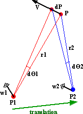
We have particle or solid object which has an angular velocity wl about point
pl when measured in local coordinates. What will be its angular velocity when
these quantities are measured in absolute coodinates? In the most general case
the transform itself may be changing itself, it may be representing a rotating
frame-of-reference about a different point than the centre of the local rotation.
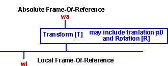
As shown here  =
=  x
x 
So when we are working in absolute coordinates:
 a
=
a
=  a
x
a
x  a
a
and when we are working in local coordinates:
 l
=
l
=  l
x
l
x  l
l
So, substituting this in the above equations:
 a
x
a
x  a
= [T1](
 l
x
l
x  l)
+ [T2]
 l
+
l
+  r
r
Here I am stuck. can anyone help me continue? I think I am making incorrect
assumptions here because the angular velocity of a solid object is just the
rate of change of its orientation. The angular velocity of a particle on the
object takes into account both the translation and the orientation of the object.
So the angular velocity of a solid object and its component particles is different.
If the frame of reference is rotating about  l=
l= a
then the angular velocities can be added:
 a
=
a
=  l
+
l
+ r
r
So although the frame-of-reference is moving about a different centre than
the point is rotating, the absolute rotation is still the sum of the roations
of the f-of-r and the local rotation. The actual motion may follow a much more
complex path. See the following examples:
Thank you to the following for helping me with this:
Further information about angular velocity.
Method using Curl
I would like to try and prove that  a
=
a
=  l
+
l
+ r
using vector calculus.
Given that  a
=
a
=  l
+
l
+ r
r
It is shown here that, for a solid
object, that curl( a)
= 2
  a
a
So if curl(a + b) = curl(a) + curl(b) we could prove that  a
=
a
=  l
+
l
+ r
r
The trouble is I can't find any indentity like curl(a + b) = curl(a) + curl(b)?
Can anyone help me?
Angular Acceleration ( )
)
As with angular velocity, the absolute angular acceleration is the sum of the
angular acceleration of the frame-of-reference and the local angular acceleration:
 a
=
a
=  l
+
l
+ r
r
This site may have errors. Don't use for critical systems.


![]() a
= [T]
a
= [T]![]() l
l


