We use the term "Euler Angle" for any representation of 3 dimensional rotations where we decompose the rotation into 3 separate angles. When we first start to think about 3D rotations this seems the natural way to proceed but our intuition can be deceptive and there are a lot of problems that arise when we use Euler angles to do calculations.
If you are reading this page in order to write a 3D computer program I suggest you read enough of this page to convince yourself of the problems with Euler angles and to get an intuitive understanding of 3D rotations and then move on to quaternion or matrix algebra representations.
On this page we will also consider theoretical issues such as the number of degrees of freedom in rotations.
Standards Used on this page
As we shall see, there is no single set of conventions and standards in this area, therefore I have chosen to adopt the following to be consistent across this site.
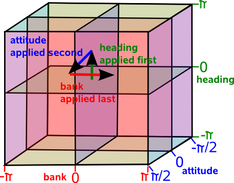
| angle applied first | heading |
|---|---|
| angle applied second | attitude |
| angle applied last | bank |
Right hand coordinate system (for both coordinates and rotations) and angles measured in the frame of reference of the rotating object.
Other websites and books that you come across will use different standards, I cant be compatible with them all, so when I setup the site I chose the conventions which seemed the most popular, that's the best I can do. The standards we choose depends on the properties we want, I have discussed the standards for this website here. See this page for an explanation of the conventions and standards used on this site.
Examples
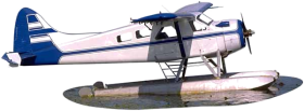
| Aircraft | Telescope |
|---|---|
 |
|
adapted from a diagram from Andy |
 |
| In this example we would naturally measure the angles in the frame of reference of the aircraft. | In this example we might think that it would make sense to measure the angles with reference to the ground. However the third angle 'tilt' is around the axis of the telescope. It is hard to find an example where all 3 angles are measured relative to the ground. |

Types of Euler Angle and Notations
Because, when we are combining rotations, order is important so there are many types of Euler angles. So when we must choose:
- Order of combining angles.
- Relative to rotating object or absolute coordinates.
- Left or right hand rotation.
- Notation for angles.
Unfortunately there is not a widely accepted set of standards so I have tried to combine what standards there are so that we can have consistency across the site.
Order of combining angles.
As a quick shorthand lets use x to represent a pure rotation about the x axis and y to represent a pure rotation about the y axis and so on. so we could represent the order of 3D rotations as: xyz, yzx, zxy or reversing the order zyx, xzy, yxz which gives 6 permutations. There are more because the angles are not independent for instance rotating 90° around x followed by 90° around y then back -90° around x is the same as a single rotation of 90° around z, so we can form any 3D rotation by combining rotations in just 2 planes, but we may have to apply 2 separate rotations in one of the planes. This means that we can also use any of the following sequences: xyx, xzx, yxy, yzy, zxz and zyz. So altogether we have 12 possible angle sequences.
Relative to rotating object or absolute coordinates.
We could measure each of the 3 angles relative to the ground (or some absolute coordinate system) or relative to the object being rotated. So the number of permutations of options goes up from 12 to 24. Our first intuition would probably measure all angles relative to the ground especially if we were writing a computer simulation or game where everything is represented in absolute coordinates. However, as we can see from the examples above, it usually makes sense to measure the angles in the coordinates of the object itself. This has the additional advantage that if we need to calculate the physics (dynamics) of the object then the inertia tensor is in the frame of the object.
Left or right hand rotation.
I don't mean the left or right handedness of the coordinate system I mean the direction along the rotation axis that we consider to be positive. For example, if we are using a right hand coordinate system, then if the thumb of our right hand indicates the direction of the positive rotation axis then the fingers show the direction of rotation.
Notation for angles.
We tend to give the different angles different names depending on the situation where we are using them. Here are some examples:
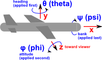
| airplane | telescope | symbol | angular velocity | ||
|---|---|---|---|---|---|
| applied first | heading | azimuth | θ (theta) | yaw | |
| applied second | attitude | elevation | φ (phi) | pitch | |
| applied last | bank | tilt | ψ (psi) | roll |
Successive Rotations
If we have a 3D rotation represented by 3 Euler angles (a1,a2,a3), and then we apply an additional rotation represented by another 3 Euler angles (b1,b2,b3), how do we calculate an equivalent set of 3 Euler angles (c1,c2,c3) which will represent these two successive rotations? This turns out to be very difficult we can't just add the corresponding angles because (c1,c2,c3) is not necessarily (a1+b1,a2+b2,a3+b3) due to the fact that the order of successive rotations is significant, for example
- Rotate 90°s about x axis
- Rotate 90°s about y axis
- Rotate -90°s about x axis
This gives 90° rotation about Z axis,
whereas
- Rotate 90°s about x axis
- Rotate -90°s about x axis
- Rotate 90°s about y axis
This gives 90° rotation about y axis (first 2 lines cancel out).
Because this is so difficult, it is usual to convert to matrix notation or quaternions and calculate the product and then convert back to euler angles. But if this is done many times the rounding errors of all these conversions will build up, leading to distortions. So if we need to do a lot of such calculations it may be best to work entirely in matrices or quaternions even though they are less intuitive than Euler angles.
I can think of different ways to combine rotations so I have put a discussion of this here.
Rotation about single axis
First we will consider rotation purely about each of the three axes individually, then we will consider the different ways of combining them.
Attitude (About Z axis)
First assume a rotation purely around the z axis, measuring from the x axis, as shown here:
In order to combine rotations using matrices we need to be clear about what conventions that we are using. The coordinate directions are represented by a right hand coordinate system and the rotation directions are represented by a the right hand rule . The identification of cells of matrix and ordering of rows and columns (as explained here) is as follows:
|
= |
|
|
So point x=1, y=0, z=0
is transformed to x=cos(attitude), y =sin(attitude) , z=0
and point x=0, y=1, z=0
is transformed to x=-sin(attitude), y =cos(attitude) , z=0
so the complete matrix for rotation about the z axis is:
| [R1] = |
|
About z axis using axis angle
Axis = (0,0,1) Angle =φ
About z axis using quaternions
The axis-angle above can be converted to quaternion as described here.
cos(φ/2) + (0 i + 0 j + 1k) * sin(φ/2)
cos(φ/2) + k * sin(φ/2)
Heading (About Y axis)
Similarly rotation about the y axis, measuring from the z axis, gives:
So point x=1, y=0, z=0
is transformed to x=cos(heading), y =0, z=- sin(heading)
and point x=0, y=0, z=1
is transformed to x=sin(heading), y=0, z =cos(heading)
so the complete matrix for rotation about the z axis is:
| [R2] = |
|
About y axis using axis angle
Axis = (0,1,0) Angle =θ
About y axis using quaternions
The axis-angle above can be converted to quaternion as described here.
cos(θ/2) + (0 i + 1 j + 0k) * sin(θ/2)
cos(θ/2) + j * sin(θ/2)
Bank (About X axis)
and rotation about the x axis, measuring from y, gives:
So point x=0, y=1, z=0
is transformed to x=0, y=cos(bank), z =sin(bank)
and point x=0, y=0, z=1
is transformed to x=0, y=-sin(bank), z =cos(bank)
so the complete matrix for rotation about the x axis is:
| [R3] = |
|
About x axis using axis angle
Axis = (1,0,0) Angle =ψ
About x axis using quaternions
The axis-angle above can be converted to quaternion as described here.
cos(ψ/2) + (1 i + 0 j + 0 k) * sin(ψ/2)
cos(ψ/2) + i * sin(ψ/2)
Example
Imaging you are in a cuboid room, you on the floor of one corner looking along along the base of one wall, you want to turn to look at the top of the opposite corner. What angle do you have to turn through?
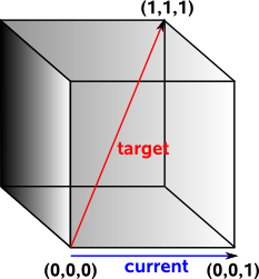
Most people would say that you would need to turn through a heading of 45° and then rotate up at an attitude of 45°. This belief is so strong that programmers will spend days rewriting and debugging their code if they don't get this answer.
In fact we need to turn through a heading of 45° and then rotate up at an attitude of 35°. You turn through 45° and you are now looking at the base of the diagonal corner. You now want to look up to the top of the diagonal side. This forms a triangle where the adjacent side is √2 and the opposite side is 1. So the angle is arctan(0.7071)=35°.
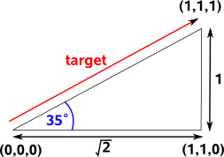
This is a warning not to trust intuition when working with 3D angles and avoid using euler angles whenever possible. (see lookat method for other methods)
Linearising Rotations
The following shows that we can't linierise rotations in 3 dimensions, I'm not sure about introducing such complicated diagrams to show what does not work, so feel free to skip this section. I just wanted to investigate why we need to introduce a 4th dimension at least (see quaternions) if we want to linearise rotations.
In order to investigate the non-linear nature of Euler rotations we can try showing the angles on a linear 3D grid and mapping the rotations onto it.
The first issue is that we must apply the angles in a given order (rotations are in local coordinates), in the example below we rotate heading 90° (2a) followed by attitude 90° (3a) and the aircraft is going up with the rudder pointing toward us, however if we rotate attitude 90° (2b) followed by heading 90° (3b) and the aircraft is going away from us with the rudder to the left..
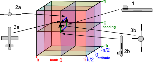
I think we can still use this diagram but we have to be careful to interpret it as implying an order and we cannot change the order.
Another example below shows that just by rotating the heading and attitude we can produce a bank.
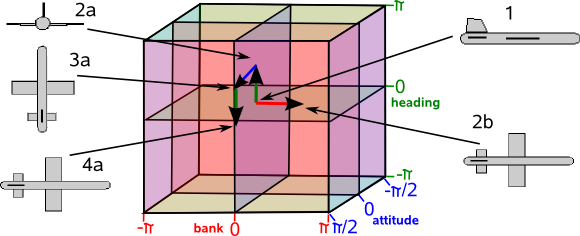
But again this is not valid on this diagram because we have altered the order of the Euler angles. All this really shows is that we cannot add the angles if we are combining them in different orders.
Even if we do apply the angles in our chosen order it does not necessarily mean that each point on the diagram represents a unique rotation, it may be that the same rotation is represented at several places on the diagram, this happens at the singularities attitude= ±π/2.
So can we distort this model so that it becomes linear? I don't know the answer to this, I suspect we need to investigate the mathematics of topology and manifolds which I have started on this page, I would welcome any help with this. I think that we can't linearise in 3D which is why we need to embed in a higher dimensional space (such as quaternions) but I don't know how to prove this.
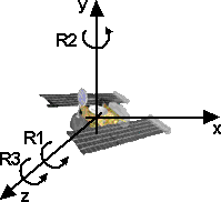
NASA Standard Aeroplane
In order to try to explain things I thought it might help to work out a simple case where rotations are only allowed in multiples of 90°s. This should make it easier to illustrate the orientation with a simple aeroplane figure, we can rotate this either about the x,y or z axis as shown here. There is also a program to show the orientations for any Euler angles.
|
adapted from a diagram from Andy |
angles:
Coordinate System: right hand Order: heading,attitude then bank (about y,z then x) Method for combining rotations: local coordinate system [resulting transform] = [first rotation] * [second transform] Singularity at θ attitude = +- PI/2 normal range:
|
|
Note: I cant find a definition of this standard, but I think it uses a slightly different coordinate definition from VRML (z and y axis swapped). Also when working with aeroplanes we often work in terms of the position of external objects relative to the aircraft (i.e. the inverse of its position transform as explained here). therefore to get the expression normally used with NASA aeroplane we invert all inputs (change sign of every term with odd number of sine terms) invert output (transpose matrix) swap z and y for inputs (swap z and y columns) swap z and y for outputs (swap z and y rows). This gives the matrix which is quoted for NASA aeroplane, which is:
The derivation of this is shown here. However, for this site I think it is better to use the transform derived below as that is in the form which compatible with the rest of this site. |
This gives a combined transformational matrix of,
[R] = [R3][R2][R1] = ([Ry][Rz])[Rx]
This is expanded out here. To save space cos(bank) is written as cb and so on:
| [R] =( | heading (rotate about y)
|
* | attitude (rotate about z)
|
) * | bank (rotate about x)
|
first multiply first two terms (for matrix multiplication see here) Remember order of matrix multiplication is significant.
| ch*ca | -ch*sa | sh |
| sa | ca | 0 |
| -sh*ca | sh*sa | ch |
then multiply by bank:
| ch*ca | -ch*sa*cb + sh*sb | ch*sa*sb + sh*cb |
| sa | ca*cb | -ca*sb |
| -sh*ca | sh*sa*cb + ch*sb | - sh*sa*sb + ch*cb |
related pages:
Preferred values and Singularities
In mathematics there are different types of singularity, in these cases we are talking about the situation where:
- Many points in one representation are mapped onto a single point in another representation.
- Infinitesimal changes close to the singularity in one representation may cause large changes in the other representation.
Using the standards that we have chosen to use the singularity is at:
θ=±π/2
Other types of Euler angles will have singularities at different places, there may therefore be good reasons to use other types of Euler angle, as it may help to put the singularity at a position were it is less likely to be encountered.
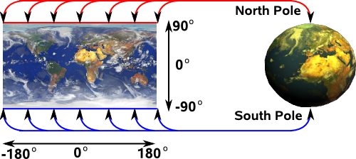
The translation between euler and quaternion is inherently many to one. To explain this, lets use a different case using only 2 angles, imagine using latitude and longitude to define a point on the surface of the earth. Normally longitude goes from 0 to 360 degrees (i.e. round the equator) and latitude goes from 90° (north pole) to –90° (south pole).
This analogy is explained in more detail on this page.
If we are at latitude =0, longitude =0 on the equator and we want to goto the opposite point on the earth we would normally describe this as latitude =0, longitude =180 (i.e. round the equator) however we could describe the same point as latitude =180, longitude =0 (over the pole). Now imagine that we have another method of describing the point on the opposite side of the earth (say using quaternions) and we want to convert this to latitude, longitude. We have no way to know which path was taken so we always use latitude =0, longitude =180 i.e. within the normal range.
Latitude and longitude also illustrates singularities at latitude 90 (north pole) and –90 (south pole). At these points longitude does not matter so if we are converting some other description of north pole to latitude, longitude it might give any value for longitude, for example, infinity. So we have to be very careful at these points.
Similarly we can map Euler angles to quaternions (4 dimensional hypersphere). This maps a one dimensional space (rotations around 0,1,0 axis) to a two dimensional plane in Euler terms. This is where attitude = 90° and heading, bank vary:
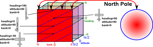
On this plane lines of common orientation are diagonal lines, that is rotation around 0,1,0 axis are given by angle = heading+bank.
Similarly for the south pole.
More information about specifying locations on earth.
Standard Aeroplane using axis angle
We cant combine axis angles directly so we have to convert to quaternions, then combine them, then convert back to axis angle as described here.
Standard Aeroplane using quaternions
We can multiply the quaternions in order, as we did with the matricies:
(cos(ψ/2) + i * sin(ψ/2)) * (cos(θ/2) + j * sin(θ/2)) * (cos(φ/2) + k * sin(φ/2))
multiplying out the terms gives:
c(ψ/2)c(θ/2)c(φ/2)
+ s(ψ/2)s(θ/2)s(φ/2)
+ i (c(ψ/2)c(θ/2)s(φ/2)
- s(ψ/2)s(θ/2)c(φ/2))
+ j (c(ψ/2)s(θ/2)c(φ/2)
+ s(ψ/2)c(θ/2)s(φ/2))
+ k (s(ψ/2)c(θ/2)c(φ/2)
- c(ψ/2)s(θ/2)s(φ/2))
related pages:
Global Frame of Reference
[z]([y][x])
| [R] = | rotate about z (last rotation)
|
* ( | rotate about y (second rotation)
|
* | rotate about x (first rotation)
|
) |
| [R] = |
|
* |
|
| [R] = |
|
NASA Standard Aerospace
 |
angles:
Coordinate System: right hand Order: z,y,z = [R3][R2][R1] |
In this case there is no individual rotation around the x axis, but the combination of rotation about the z axis and a rotation about the y axis can produce a rotation about the x axis, so a rotation about z then y then z can produce any possible rotation.
| [R1] = |
|
| [R2] = |
|
| [R3] = |
|
This gives a combined transformational matrix of,
[R] = [R3][R2][R1]
This is expanded out here. To save space cos(precession) is written as c ψ and so on:
| [R] = |
|
|
|
first multiply second two terms (for matrix multiplication see here) Remember order of matrix multiplication is significant.
| [R] = |
|
|
| [R] = |
|
related pages:
The singularity is at:
![]()
The Quaternion is:
![]() + i (
+ i (![]() )
+ j (
)
+ j (![]() ) + k (
) + k (![]() )
)
related pages:
sfrotation
On these pages will be developing a class sfrotation (full listing here) which holds a rotation, in addition to coding the rotation as axis angle it can also be coded as euler or quaternion and can convert between these formats.
Further Reading
You may be interested in other means to represent orientation and rotational quantities such as:
Or you may be interested in how these quantities are used to simulate physical objects:
