Prerequisites
Euler Angles are one possible way to represent the orientation, or other rotational quantity, associated with a solid 3D object.
If you are not familiar with this subject you may like to look at the following pages first:
Types of Euler Angle
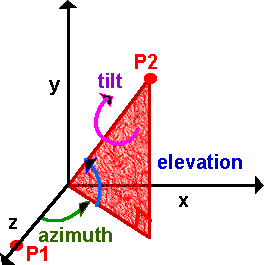
In 3D rotation there are 3 degrees of freedom. Shown here as 3 angles, azimuth, elevation, and tilt. For example, if you were aiming a gun you would raise the barrel by a certain angle (elevation). Turn it in the direction required (azimuth). And if the barrel has rifled then the projectile will spin about its axis (tilt). In other areas, say nautical, different terms may be used such as roll, pitch and yaw.
Its not just the names of the angles that changes in different Euler angle conventions, there is also the order that the angles are applied (in mathematical terms rotations are not commutative), and also whether the rotations are left or right handed. One possibility would be:
- rotate counterclockwise about x axis by a1
- then rotate counterclockwise about y axis by a2
- then rotate counterclockwise about z axis by a3
In order to specify any arbitrary rotation it is not necessary that the rotation axis to be at right angles, in fact two of the 3 axis could be the same and we could still define an arbitrary rotation with 3 angles. For example:
- Rotate 90 degrees about x axis
- Rotate 90 degrees about y axis
- Rotate -90 degrees about x axis
This gives 90 degree rotation about Z axis, even though no individual rotations have been done about the Z axis.
Even if we ignore non-90 degree coordinates, there are 12 possible angle sequences which would represent any possible 3D rotation by specifying 3 angles which might be about the x, y, or z axies,
- 6 with mutually perpendicular rotation axis: (x y z, x z y, y x z, y z x, z x y and z y x)
- 6 with angle 3 in the same axis as angle 1: (x y x, x z x, y x y, y z y, z x z and z y z)
Here we will only consider 3 of these possible combinations known as, NASA Standard Aeroplane and NASA Standard Aerospace and also NASA standard Aeroplane in reverse order.
Successive Rotations
If we have a 3D rotation represented by 3 Euler angles (a1,a2,a3), and then we apply an additional rotation represented by another 3 Euler angles (b1,b2,b3), how do we calculate an equivalent set of 3 Euler angles (c1,c2,c3) which will represent these two successive rotations? This turns out to be very difficult we can't just add the corresponding angles because (c1,c2,c3) is not necessarily (a1+b1,a2+b2,a3+b3) due to the fact that the order of successive rotations is significant, for example
- Rotate 90 degrees about x axis
- Rotate 90 degrees about y axis
- Rotate -90 degrees about x axis
This gives 90 degree rotation about Z axis,
whereas
- Rotate 90 degrees about x axis
- Rotate -90 degrees about x axis
- Rotate 90 degrees about y axis
This gives 90 degree rotation about y axis (first 2 lines cancel out).
Because this is so difficult, it is usual to convert to matrix notation or quaternions and calculate the product and then convert back to euler angles. But if this is done many times the rounding errors of all these conversions will build up, leading to distortions. So if we need to do a lot of such calculations it may be best to work entirely in matricies or quaternions even though they are less intuitive than Euler angles.
I can think of different ways to combine rotations so I have put a discussion of this here.
Rotation about single axis
First we will consider rotation purely about each of the three axes individually, then we will consider the different ways of combining them.
About Z axis
First assume a rotation purely around the z axis, measuring from the x axis, as shown here:
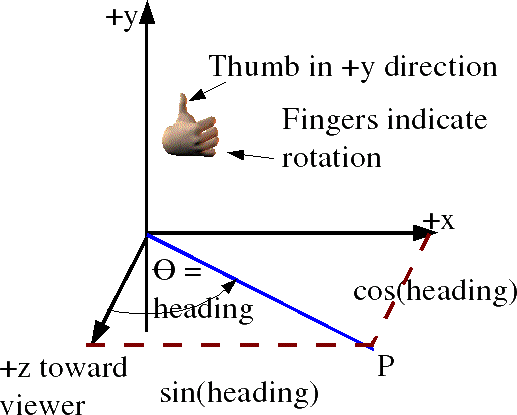
In order to combine rotations using matricies we need to be clear about what conventions that we are using. The coordinate directions are represented by a right hand coordinate system and the rotation directions are represented by a the right hand rule . The identification of cells of matrix and ordering of rows and columns (as explained here) is as follows:
|
= |
|
|
So point x=1, y=0, z=0
is transformed to x=cos(heading), y =sin(heading) , z=0
and point x=0, y=1, z=0
is transformed to x=-sin(heading), y =cos(heading) , z=0
so the complete matrix for rotation about the z axis is:
| [R1] = |
|
About z axis using axis angle
Axis = (0,0,1) Angle =φ
About z axis using quaternions
The axis-angle above can be converted to quaternion as described here.
cos(φ/2) + (0 i + 0 j + 1k) * sin(φ/2)
cos(φ/2) + k * sin(φ/2)
About Y axis
Similarly rotation about the y axis, measuring from the z axis, gives:
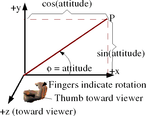
So point x=1, y=0, z=0
is transformed to x=cos(heading), y =0, z=- sin(heading)
and point x=0, y=0, z=1
is transformed to x=sin(heading), y=0, z =cos(heading)
so the complete matrix for rotation about the z axis is:
| [R2] = |
|
About y axis using axis angle
Axis = (0,1,0) Angle =θ
About y axis using quaternions
The axis-angle above can be converted to quaternion as described here.
cos(θ/2) + (0 i + 1 j + 0k) * sin(θ/2)
cos(θ/2) + j * sin(θ/2)
About X axis
and rotation about the x axis, measuring from y, gives:
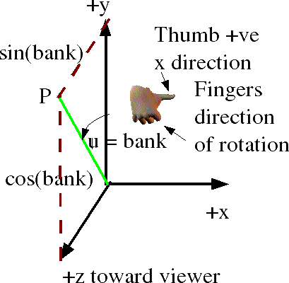
So point x=0, y=1, z=0
is transformed to x=0, y=cos(heading), z =sin(heading)
and point x=0, y=0, z=1
is transformed to x=0, y=-sin(heading), z =cos(heading)
so the complete matrix for rotation about the x axis is:
| [R3] = |
|
About x axis using axis angle
Axis = (1,0,0) Angle =ψ
About x axis using quaternions
The axis-angle above can be converted to quaternion as described here.
cos(ψ/2) + (1 i + 0 j + 0 k) * sin(ψ/2)
cos(ψ/2) + i * sin(ψ/2)
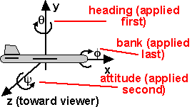
NASA Standard Aeroplane
adapted from a diagram from Andy |
angles:
Coordinate System: right hand Order: z,y,x = [R3][R2][R1] |
This gives a combined transformational matrix of,
[R] = [R3][R2][R1]
This is expanded out here. To save space cos(precession) is written as c ψ and so on:
| [R] = |
|
|
|
first multiply second two terms (for matrix multiplication see here) Remember order of matrix multiplication is significant.
| [R] = |
|
|
| [R] = |
|
related pages:
The singularity is at:
θ=±π/2
Standard Aeroplane using axis angle
We cant combine axis angles directly so we have to convert to quaternoins, then combine them, then convert back to axis angle as described here.
Standard Aeroplane using quaternions
We can multiply the quaternions in order, as we did with the matricies:
(cos(ψ/2) + i * sin(ψ/2)) * (cos(θ/2) + j * sin(θ/2)) * (cos(φ/2) + k * sin(φ/2))
multiplying out the terms gives:
c(ψ/2)c(θ/2)c(φ/2)
+ s(ψ/2)s(θ/2)s(φ/2)
+ i (c(ψ/2)c(θ/2)s(φ/2)
- s(ψ/2)s(θ/2)c(φ/2))
+ j (c(ψ/2)s(θ/2)c(φ/2)
+ s(ψ/2)c(θ/2)s(φ/2))
+ k (s(ψ/2)c(θ/2)c(φ/2)
- c(ψ/2)s(θ/2)s(φ/2))
related pages:
Sample Rotations
In order to try to explain things I thought it might help to work out a simple case where rotations are only allowed in mutiples of 90 degrees. This should make it easier to illustrate the orientation with a simple aeroplane figure, we can rotate this either about the x,y or z axis as shown here:
reference orientation φ = 0 |
rotate by 90 degrees about x axis φ = 90 degrees |
rotate by 180 degrees about x axis φ = 180 degrees |
rotate by 270 degrees about x axis φ = -90 degrees |
|||
rotate by 90 degrees about z axis φ = 0 |
rotate by 90 degrees about y axis φ = 0 |
|||||
rotate by 180 degrees about z axis φ = 0 |
rotate by 180 degrees about y axis φ = 0 |
|||||
rotate by 270 degrees about z axis φ = 0 |
rotate by 270 degrees about y axis φ = 0 |
When we combine these rotations about the x,y and z axies in 90 degree multiples there are 24 possible orientations as shown here:
φ = 0 |
φ = 90 degrees |
φ = 180 degrees |
φ = -90 degrees |
φ = 0 |
φ = 0 |
φ = 0 |
φ = 0 |
φ = |
φ = 90 degrees |
φ = 180 degrees equivilant rotation to φ = 0 degrees |
φ = -90 degrees |
φ = 0 |
φ = 0 |
φ = 0 |
φ = 0 |
φ = 0 |
φ = 0 |
φ = 0 |
φ = 0 |
φ = 0 |
φ = 0 |
φ = 0 |
φ = 0 |
encoding of these rotations in quaternions is shown here.
encoding of these rotations in matricies is
shown here.
encoding of these rotations in axis-angle is
shown here.
NASA Standard Aeroplane (reversed order)
adapted from a diagram from Andy |
angles:
Coordinate System: right hand Order: x,y,z = [R1][R2][R3] |
This gives a combined transformational matrix of,
[R] = [R3][R2][R1]
| [R] = |
|
|
|
multiplying matricies gives:
| [R] = |
|
related pages:
Standard Aeroplane (reversed) using quaternions
We can multiply the quaternions in order, as we did with the matricies:
(cos(ψ/2) + k * sin(ψ/2)) * (cos(θ/2) + j * sin(θ/2)) * (cos(φ/2) + i * sin(φ/2))

related pages:
NASA Standard Aerospace
 |
angles:
Coordinate System: right hand Order: z,y,z = [R3][R2][R1] |
In this case there is no individual rotation around the x axis, but the combination of rotation about the z axis and a rotation about the y axis can produce a rotation about the x axis, so a rotation about z then y then z can produce any possible rotation.
| [R1] = |
|
| [R2] = |
|
| [R3] = |
|
This gives a combined transformational matrix of,
[R] = [R3][R2][R1]
This is expanded out here. To save space cos(precession) is written as c ψ and so on:
| [R] = |
|
|
|
first multiply second two terms (for matrix multiplication see here) Remember order of matrix multiplication is significant.
| [R] = |
|
|
| [R] = |
|
related pages:
The singularity is at:
![]()
The Quaternion is:
![]() + i (
+ i (![]() )
+ j (
)
+ j (![]() ) + k (
) + k (![]() )
)
related pages:
Example
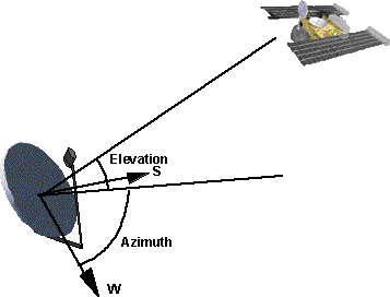
It is not always apparent that the three angles to specify a rotation are not independent of each other and must be applied in a certain order. For example imagine that we are aiming a dish at a satellite. The azimuth and elevation are independent of each other, for example we can aim south and then elevate up by the required inclination, or we can set the elevation and then turn and point toward the south. However there is a third angle, we can rotate about the line to the satellite, to correctly align with the horizontal and vertically polarised signal from the satellite, this third angle is dependant on the others so we cant escape from this issue.
When the angles are small, then they are nearly independent of each other, for example if we are aiming at a small area of sky.
sfrotation
On these pages will be developing a class sfrotation (full listing here) which holds a rotation, in addition to coding the rotation as axis angle it can also be coded as euler or quaternion and can convert between these formats.
Further Reading
You may be interested in other means to represent orientation and rotational quantities such as:
Or you may be interested in how these quantities are used to simulate physical objects:
