Abstract
An isometry transform is a combination of a translation and a rotation. On the page here we have shown that in two dimensions we represent any isometry as a single rotation provided that we choose the correct point to rotate it around.
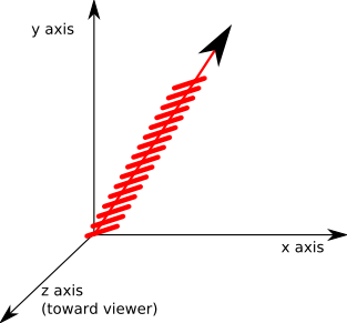
In three dimensions, if we want to represent any isometry as a single operation, a rotation about any point is a possibility, in order to represent any isometry as a single operation we could use a line drawn round the outside of a cylinder. This is known as a screw.
Combined Rotation and Translation using Screw Theory.
Isometry in 3 dimensions SE(3)
In three dimensions there are three degrees of freedom of rotation but when we look for points that are equidistant to the centres of the objects pre and post transform position. The equidistant points lie on a plane which only has two degrees of freedom, but there is also the possibility to rotate around the line from the point. Therefore there are enough degrees of freedom to represent all possible isometrys. However this has not yet proved that we can represent any 3D isometry by a single rotation, can anyone help me with this?
There is another way to represent all possible isometries in three dimensions as a single operation, even though the operation is not a rotation, the operation is represented by a line round the outside of a cylinder.
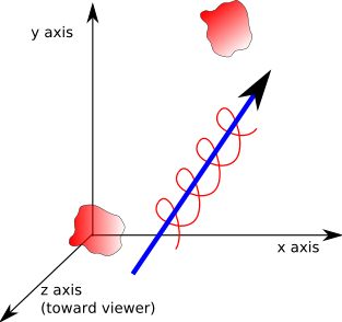
We start with a vector representing the direction of the cylinder, so there is translation along the length of the cylinder and this is in the same direction as the axis of rotation. This is like a screw thread in that, as the object turns, it moves in a linear direction. The amount of linear movement for a given rotation is called the pitch.
- If the pitch is zero (0) then the object has pure rotation.
- If the pitch is infinity (∞) then the object has pure translation.

This is alright if the object is rotating around the direction that it is traveling (like a rifle bullet for example) but what if the object is rotating end-over-end?
We can represent any 3D translation/rotation by allowing the axis to be offset from the origin. This means that the object can be translated through a screw path:

This line can be represented in alternative ways:
- As two vectors: a direction vector and an offset vector representing a point on the line.
- As two vectors: representing two points on the line.
- As Plucker coordinates.
Specifying Using Plucker Coordinates
As explained on this page a line which does not go through the origin (known as a directed line) can be defined with plücker coordinates. This has the advantage that it does not need us to choose arbitrary points on the line to define it. Therefore two identical lines may be specified differently and so we can easily check if the lines are identical or how close they are to each other.
Plücker coordinates are written in this form:
(v ; P x v)
The semicolon ';' distinguishes it from a 6 dimensional vector.
where:
- v : unit vector (normalised to unit length)
- P x v : known as the 'moment' its direction is mutually perpendicular to both the vector and to the shortest distance between the origin and the line.
When used to define a line in this way the 'moment' part does not have a component in the direction of v. So we can also use this vector to hold information about the pitch by adding this on to the moment, therefore the complete information about the translation&rotation is given by:
(v ; P x v + v*pitch)
where:
- v : unit vector (normalised to unit length) in direction of linear component.
- P : a point on the line
- pitch : pitch of screw in radians
Example
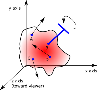
Express the following forces and torques as Plücker coordinates:

- A: a force of 12 Newtons at point (1,6,1) in direction (0.7071,0.7071,0)
- B: a torque of 9 Newton-metres at point (5,5,4) along the axis (0.7071,0.7071,0)
- C: a force of 7 Newtons at point (1,1,-1) in direction (0,-0.7071,0.7071)
- D: a force of 15 Newtons at point (6,2,2) in direction (0,0.7071,0.7071)
Applications
Screw theory can be used in solid body mechanics for representing systems of forces and also for representing combined angular and linear velocities.
Further Reading
You may be interested in other means to represent orientation and rotational quantities such as:


