Physics - Forum - Impulse

By: Richard - redeyes2003
file Rigid body physics  
2004-07-01 19:28

I am working on the solution to a problem: A rigid body receives an impulse of a force, such as in a collision. The case involves any free rigid body which can be bombarded by a particle, causing a change in momentum of the rigid body. However, the force, causing the momentum change, does not necessarily act through the centre of mass in the rigid object, so rotation is at play. I need to know what position/orientation the rigid body will have any time after the impact. The mass and inertia of the rigid body is known, and so too is the position, direction and magnitude of impulse.

Are there any links on the topic and what is the solution? I am trying to use the functionality for the basic of a class of single rigid bodies. I hope the topic is not too far off from what is discussed here.

I am using a temporary "guess" algorithm, that seems to at least behave right but I would like the real simulation. :^)

By: Richard - redeyes2003
file RE: Rigid body physics  
2004-07-01 19:46

Oh never mind, I think I may have found the answer at
https://www.euclideanspace.com/physics/dynamics/inertia/index.htm

I am going to do some reading 8:^)

By: Richard - redeyes2003
file RE: Rigid body physics  
2004-07-02 20:28

Hi Martin, I have not gotten the idea of what to do about the problem I was inquiring. I have looked at

leftcue.htm

and

inertia/index.htm

and I was unclear on how to calculate the position/orientation after time t when an impulse acts on a rigid body. Maybe u could explain how the torque is measured, so I can know how much of the impulse goes into rotational thus the remainder would go into translational.

Anyways keep up the good work, I have enjoyed all the pages that I read, and I have veiwed a lot but not nearly 1 percent or enough of your work. Before the past month, I thought there was not anything to learnt, now I felt that I have not learnt much at all. Your work is great! Keep teaching me.

PS.
The "guess" equation that i used is:
Translational = Io/(Io + M.l.l)
Rotaional = M.l.l/(Io + M.l.l)
where Io is inertia about C.M axis
M is mass of rigid body
l is the perpendicular distance from force to the C.M

By: Martin Baker - martinbaker
file RE: Rigid body physics  
2004-07-03 02:04

Hi Richard,

Thanks for your kind comments about the website.

I don't claim to have the answer to your question, but I think I would try applying the following principles:

We want to calculate the motion of the rigid body after the impulse as the sum of the linear motion of its centre of mass and its rotation about its centre of mass.

I think its linear motion is simple, since F = ma = m dv/dt this gives:
Change in velocity = dv = (F/m) dt = impulse/m
So the linear motion will be in the same direction as the impulse, even if the impulse is applied at a point offset from the centre of mass, this seems counter intuitive and this is what I have been trying to get to grips with in the various examples on the website. I think the is correct however, I think that this does not correspond to our intuition because in a practical collision the impulse is not necessarily in the direction of the impact but will have a component which is normal to the surface of the colliding objects.

We then need to calculate the rotation:
I think we could have an equivalent to Newtons 3rd law for impulses, in other words: every impulse has an equal and opposite impulse. If we apply the impulse to an object which is not attached to anything else then I think this equal and opposite reaction would act on the centre of mass.

Perhaps we could have an angular equivalent of impulse as follows:
Linear impulse = integral(Force) dt = change of linear momentum
Angular impulse = integral(Torque) dt = change of angular momentum
However I think we have to be careful here because in the linear case:
F=ma where m=mass which is a scalar quantity
but in the angular case we have:
T = [I] angAcc where [I] = inertia tensor which is a 3x3 matrix

So is it valid to say that:
Change in angular velocity = [I]-1 angular impulse
Where:
* [I]-1 = the inverse of the inertia tensor in global coordinates (which will change as the object rotates)
* angular impulse = Linear impulse x d
* d = distance between c of m and point where impulse is applied (which is a 3D vector quantity)
* x = vector cross product
* Linear impulse = 3D vector quantity

I am not really sure about all of this, what I really need is someone to help me apply some mathematical rigor to this so that I can then have some confidence to apply this to practical problems.

Martin

By: Richard - redeyes2003
file RE: Rigid body physics  
2004-07-04 01:21

Hi Martin,

I think I follow the calculations for linear and rotational independently. But you made an assumption that
"Change in velocity = dv = (F/m) dt = impulse/m"
all the impulse is used in the translation, shouldn't it be more like
"Change in velocity = dv = (F/m) dt = ftrans x impulse/m"
where ftrans is the ratio of the impulse that goes into translation.
This is evident if all the impulse went into translation, by conservation of energy there should be no rotation since this would require addition energy. I believe this is our intuition.
A similar case is that of light rectangular wooden block that is glued down on top of a table top. The glue is applied evenly and represents the opposition of motion of the block. If a force was applied to the block to cause it to be displaced, break the glue, it would be found that it is displaced easiest when the force acts near the end and not the centre. But how does this relate to our problem, I am assuming if a force is applied through the centre of mass it feels the maximum net inertia of the wood, but if the applied force passes through any other points, then it feels less inertia (or glue). Thus the reaction to this applied force would be less. Again, the reaction comes from all the particles of the wood and would be felt strongest from the centre of mass (This is analogous to all the particles of the wood that are glued down to the table which are producing a strong hold through its center). The reaction would also be felt at the ends of the block, but would be less. (When you push with your hand at an end of the block 'til it is displaced, the force feels less than if you push the block through the centre)(Let us say too that all the forces applied to the block are directed in the normals of the surfaces of the block, for simplification. So what forces applied and felt are not components).
Let's make another assumption; this one is crazy but bear with me. Let's assume that when we push on the block, there exists a pivot and that the force we are applying exerts a moment about that pivot. Then we assume that our pivot exists at a point where the moment would be at its maximum*, given the intuition that this is how the wood block is displaced by a lesser force. I am sorry; I have been talking about moments when I should have said Torque. *The 'opposition' of the glue about this pivot is included in the moment, so I am referring to the net moment.
Now at the breaking point, the pivot is at a distance r from the centre of mass and the magnitude of r is Io/(M.l) with r being on the left side of the CM when the force is applied on the right of the CM (This I will prove later). Here is the final assumption; an impulse is transmitted to a "free" wooden block by the instance of a force applied to it which torques about this pivot in that instance. Thus the "translation factor", ftrans, is given by how much the centre of mass would move in the torque when the force of the end is moved an infisemal distance.

--------------------------------------------------------
| |
X Pivot x CM
| |
--------------------------------------------------------
<----------------r--------------><-----------l------------->
^
| Impulse
|
|
|

If the diagram works, then the CM is translated by r/(r+l) of any distance that the force of the impulse travels, and if r is proven to be Io/(M.l) then the result is Io/(Io +M.l.l) of any impulse goes into translation. Intuitively, The remainder goes into the rotation of it and is M.l.l/(Io + M.l.l).
So this would be my best guess of what ratio of the impulse goes into translation.


Would u agree to a fraction of the impulse goes into translation? And the rest into rotation? You can agree to this without agreeing to the assumptions that I have made.

Finally rotation is
"T = frot x [I] angAcc" where frot is the factor that goes into rotation

By: Richard - redeyes2003
file RE: A better illustration  
2004-07-04 01:33

..........................Wooden block on table
...........--------------------------------------------------------
...........|......................................................|
X Pivot............................ x CM
...........|..................................................... |
...........--------------------------------------------------------
<-------------------r--------------><-----------l------------->
..............................................................^
..............................................................| Impulse
..............................................................|
..............................................................|
..............................................................|

By: Richard - redeyes2003
file RE: Rigid body physics  
2004-07-04 04:14

Hi Martin,

I am uncertain of the assumptions that I have made and I wish I knew what the solution was. I am in partcular afraid of the last assumption that based ftrans to the distance move by the impulse. The distane moved by force is an enegry quantity and the shorter distance moved by the CM does not imply the direct proportionality of the impulse that is transmitted to linear motion. It could very well be that
ftrans = (Io.Io)/(Io.Io + (M.l.l).(M.l.l)) ?
and
frot = ((M.l.l).(M.l.l))/(Io.Io + (M.l.l).(M.l.l)) ?

Anyway here is the proof of the position of the pivot point if there exists a pivot point:
Let at the time when the wood block is just displaced, the velocity moved is maximum for the minimum force only. The velocity is given in the line of action of the force. I am looking for when the volocity is max since a maximum velocity coincide with maximum net torque.
Let the applied force be K.
Now,


v = w * R
where
*R is distance force from pivot R=r+l and w is angular velocity, and r is the distance of the pivot point from CM and is signed (positive to the left)

w = angacc * t (t is time of impulse)

therefore,
v = angacc * t * R

but,
angacc = T/I (Newton 1st law)
*T is torque
*I is inertia

thus sustituting T and I gives,
angacc = F * R/(Io + M.r.r)
*F is our applied force of K Newtons

so,
v = (F * R/(Io + M.r.r)) * t * R
v = Ft * R/(Io + M.r.r) * R
v = K * (r+l)/((Io + M.r.r) * (r+l))

dv/dr = 0 gives r when v is maximum, ignore K because 1/K dv/dr = 0.

using,
d(A/B)dr = (B.dA/dr - A.dB/dr)/(B.B)

dv/dr = d( (r+l)/((Io + M.r.r) * (r+l)) )/dr
= ((Io + M.r.r)(2r + 2l)-(r.r + 2.l.r + l.l)(2.M.r))/((Io + M.r.r)(Io + M.r.r))

Again ignore the denominator since it is squared and is not 0 for a realistic rigid body
Thus our numerator is expanded to
2.Io.r + 2.Io.l + 2.M.r.r.r + 2.M.l.r.r - 2.M.r.r.r - 4.M.l.r.r - 2.M.l.l.r

and simplified to
2.Io.r + 2.Io.l - 2.M.l.r.r - 2.M.l.l.r

and dv/dr is 0 when,
Io.r + Io.l - M.l.r.r - M.l.l.r = 0
or
(M.l)r.r + (M.l.l-Io)r + (-Io.l) = 0

By roots of a quadratic,
r = (-(M.l.l-Io) +-sqrt[ (M.l.l - Io)(M.l.l - Io) + 4(M.l)(Io.l) ])/(2.M.l)
expanding inside the square root
r = (-(M.l.l-Io) +-sqrt[ (M.M.l.l.l.l - 2.Io.M.l.l + Io.I.o + 4Io.M.l.l) ])/(2.M.l)
simlplifying back the sqrt term
r = (-(M.l.l-Io) +-sqrt[ (M.l.l + Io)(M.l.l + Io) ])/(2.M.l)

r = (Io - M.l.l) +- (M.l.l + Io) / 2.M.l

If the positive of the square root is used then
r = 2.Io/2.M.l = Io/M.l
If the negative of the square root is used then
r = -2.M.l.l/2.M.l = -l
The latter is invalid for a maximum vel using r=-l because the force would pass through the pivot

You must be annoyed to read so much at this point, especially when its all guessing. I still would like anyone to help me out with the correct solution.

By: Martin Baker - martinbaker
file RE: Rigid body physics  
2004-07-04 07:53

Hi Richard,

I think this is one of those things that is counter intuitive, which is why I find it so difficult and I don't claim to understand it fully but I think I'm coming to a different approach than you.

I think there are 3 conservation laws that apply independently:
1) conservation of energy.
2) conservation of linear momentum
3) conservation of angular momentum
So when we have a collision, we may have energy passed between the objects, and linear momentum, and angular momentum, but we cant have energy converted into momentum and we cant have linier momentum converted into angular momentum etc.

Energy is a scalar quantity and it can be converted into different forms, kinetic, potential, heat, etc.
Linear momentum is a vector quantity and it is always conserved in a closed system, so the momentum in the x direction cannot be converted to momentum in the y direction and it cant be converted to angular momentum.

So, in a closed system, if an object looses some momentum in the x dimension, then other object(s) must gain the same amount of momentum in the x dimension. This is independent of what is happening to the energy and the angular momentum, it is even independent of the linear momentum in the y and z dimensions.

Now it seems to me that the impulse it a direct measure of the linear momentum transferred between 2 objects in a collision, i.e.
Impulse = m1 * change of velocity 1 = m2 * change of velocity 2

Its interesting that the energy and angular momentum are also conserved (I wish I could prove why that is always the case) but the impulse is more directly concerned with the conservation of linear momentum.

So I have come to the conclusion that the impulse is not somehow split between a linear and angular part, even though I agree, this seems completely counter intuitive.

Martin

By: Andy Goldstein - andygoldstein
file RE: Rigid body physics  
2004-07-04 12:08

All this discussion brings back fond memories of superballs - the real ones that came out in the late 60s, not the poor imitations available now. The original superball was characterized by a coefficient of restitution of nearly 1 and a very high surface friction. Aside from being a blast to play with, it was an excellent demonstrator of how angular and linear momentum of an individual body can be interchanged. Throw a superball with a significant backspin or overspin, and the successive bounces will cover alternately long and short strides, and the spin is reversed with each bounce and is traded for linear momentum.

Another gedanken experiment can show you how linear and angular momentum can be traded among multiple objects: Consider a rectangular bar floating in space, with two small objects moving towards the bar from opposite directions. At the same instant, opposite faces near opposite ends of the bar are struck by these objects, causing the bar to rotate.

The latter (unlike the superball) is a closed system. Linear and angular momentum are conserved, but only the total linear and angular momentum of the whole system. Where did the angular momentum come from, when before the collision there was no rotation? It came from the two small objects in the form of the lever arm represented by the distance between their paths of travel.

I'm reminded of the elastic collision problems we had to solve in freshman physics. Given the masses and initial velocities of the objects, you have total momentum and kinetic energy which must be equal before and after the collision. You solve it with a set of simultaneous nonlinear equations. Problem is when you step up to three dimensions and start taking rotation into account the number of variables goes way up. And the ways in which angular momentum can be represented are not always obvious.

Finally, remember that only total energy is conserved, not kinetic energy. All real collisions are somewhat non-elastic and some fraction of the total kinetic energy is transformed into heat (or radiated off as sound or whatever else).

- Andy

By: Richard - redeyes2003
file RE: Rigid body physics  
2004-07-04 23:09

Thanks for your ideas, Martin and Andy. I am learning new things everyday.

I am giving the conservation idea alot of thought. More than an idea, it is law. However difficult it is to "see" what is actually happening, a careful analysis of the model should give us a solution.

I do believe in,
1) conservation of energy.
2) conservation of linear momentum
3) conservation of angular momentum

Let me state,
angular momentum = mvr = mw(r.r)
linear momentum = mv

Picture a rectangulr box in space and it is bombarded by a steel ball at one of its ends. It demonstrates conservation of angular momentum, if you consider a lever to exist between the center of mass of the rectangle and the center of mass of the ball.

I guess I may have to try another approach. Mine did not work.

By: Martin Baker - martinbaker
file RE: Rigid body physics  
2004-07-05 08:03

I have found this thread very useful because it started from the idea that the impulse is known so what is the change in motion. In my past unsuccessful attempts to get a general solution for 3D collisions the impulse is one of the unknowns, I wonder if anyone has any thoughts on working back to calculating the impulse?

I guess the direction will be somewhere between:
* normal to surfaces at the point of collision (if friction is low)
* approach direction (if friction is high)

And its value will be somewhere between:
* The value required to make the velocity of the two objects after collision equal (if elasticity is low)
* The value required to make the two objects diverge at an equal and opposite velocity to which they converged (if elasticity is high)

I'm not sure this is quite right as it does not seem to properly take into account the rotation.

Ideas? - Martin

By: Richard - redeyes2003
file RE: Rigid body physics  
2004-07-05 21:34

Firstly, I would not say that calculating the impulse before hand is the best way to carry out a simulation of colliding bodies, however it is the method that I understand thus prefer. Up til now, I never attempted to find its solution.

I don't think also that it is too difficult. What I would do is name all the data we need first: the elasticity* and dampness* of the surface materials of our colliding bodies, the velocities [dx,dy,dz] /dt of the bodies, and the normal to the surface being collided.(The ideal normal would be closer to the normal of the polygon that has been virtually penetrated by the edges of other polygons), and also the coefficient of friction, maybe our time step, so we know how much impulse is during the time step.

*I am not certain of the names of these quantities, but the first one refers to a spring constant and the second one refers to the dampness in compressing/extending the spring.

In a real collision, the impacting bodies collide and each experiences a gradual change in linier momentum. The total momentum is conserved, and so too is the total energy. The simplest of the collisions involve two similar masses coming together along a straight path with equal magnitudes of their velocities, and when they do collide they are perfectly elastic, no energy is loss. At some point, their velocities are 0. Momentum is still conserved since they always have opposite directions, and the sum is 0, but where is the energy? The energy is stored as potential from the repulsion between the bodies when they are compressed at there closest distance to each other. Then the reverse occurs and the bodies continue to accelerate away and complete the collision. Their momentum must be conserved.

Now, we attempt to get the impulse of this situation.
............../
Impulse = Fdt
............../
The repulsive force of one of the bodies is a function of the distance between its CM and its surface point. Realistically, there can be compression of this distance.
Repulsive force = CM to surface distance * elasticity(*)
The elasticity itself may be a function of CM to surface distance, and it approaches infinity when CM to surface distance approaches 0 ie elasticity varies inversely.

In our algorithms, we use the impulse. The impulse which results from all of this detail is some serious integration or a simple "mv". Intuitively, any repulsion integrated over time is the same as -2mv for each body (the time interval for a collision is extremely small practically). We could spread the impulse over our time step, for a practical coding approximation and say a constant force of -2mv/T exists during the period T. So on such a collision, we add this value to our bodies for our time step.

Now we look at the same thing, but with different masses colliding (size and velocity is as previous). Imagine at collision, the same compression is experienced by both bodies (the heavier body is not completely repelled when the lighter is completely repelled by the same magnitude of the repulsion force). Thus, upon separation, the larger body experiences less than -2mv impulse where m is its mass. The smaller body experiences -2mv where m is its mass. Conservation of momentum and energy is important. What is the impulse experienced by each object?
Firstly total momentum = m1.v1 + m2.v2
Total energy = ½ m1.v1.v1 + ½ m2.v2.v2
Given that v2 after collision is -v2 for the lighter body we can calculate the new velocity of the heavier body. The impulse felt by the larger body is expected to be the same magnitude as that experienced by the smaller body. Again we add the impulse for our time step.

Now we look at a new case which is similar to the first case we talked about. The masses are the same but the velocities are different. On collision the faster mass pushes the surface of the lighter body closer to its CM(of lighter body) than it would have in our first case. Thus the second body attains a greater magnitude in velocity than what it started with. Perhaps the new velocity of body 2 is dependent on the initial speeds and how quickly the surface can be compressed or the length of how much it needs to be compressed to experience the same repulsion. Anyway, the conservation of momentum and energy is satisfied.

I have just laid down an introduction, and I am sorry to have it incomplete, and to not answer any of your questions, Martin. I need to verify some stuff.

By: Richard - redeyes2003
file RE: Rigid body physics  
2004-07-06 01:36


I found some errors in my previous method. No conservation of angular momentum. No conservation of linear momentum. Etc.

Consider our impulse, Fdt

In dt, the force is assumed to produce a torque about the pivot point,
..and

T = F x R = F x (r + l)

..while the angular acceleration

a = T/I .........................(I is assumed scalar for now)
a = F * (r + l)/(Io + M.r.r).....(sustituting T = Fx(l+r) and I = Io+M.r.r by the parrallel axis theorem)

..the change in angular velocity
dw = Fdt * (r + l)/(Io + M.r.r)

..the change in velocity that occurs in the force direction and position
dv = dw.R = dw.(r + l)
dv = (Fdt * (r + l)/(Io + M.r.r)).(r + l)
dv = Fdt * (r + l).(r + l)/(Io + M.r.r)

..the change in linear velocity of the CM of the object
dv_cm = dv * r/(r + l)
dv_cm = (Fdt * (r + l).(r + l)/(Io + M.r.r)) * r/(r + l)
dv_cm = (Fdt * (r).(r + l)/(Io + M.r.r))

..thus the change in position after dt
dx = v_cm.dt+(0.5*dv_cm.dt)...............(From Newtons equation of motion)

..therefore the next position is
x_next = x + dx

Let us see if this equation satisfy the condition of the force applied to the center of the wood, l = 0
.....r = Io/(M.l)
.....r = infinity
.....dv_cm = Fdt * (r).(r + l)/(Io + M.r.r)
.....dv_cm = Fdt * (r).(r)/(Io + M.r.r)
.....dv_cm = Fdt * (1/M)...................(By continuty as r => infinity)


How did I come to the conclusion that the maximum linear (and not angular velocity) dictated where the instantaneous pivot was, and that the linear velocity must be measured in the line of the force?

The instantaneous pivot must be such that it applies to the minimum linear force needed to displace the wood yet the maximum linear acceleration in the line of the force when the body is free. (Think about what happens when scaling the glue down to zero and reducing the force to maintain the equilibrium just before the wood 'pops', then increasing the force. The acceleration, in the line of the force, is caused by the force-It is the force which produces a torque-A torque which produces an angular acceleration-An angular acceleration which produces a linear acceleration)

The linear acceleration(a) is proportionate to the change in linear velocity(v).
So I could have used da/dr instead of dv/dr = 0 to find r, for any constant force.
However, the relationship between velocity and the force is not as obvious. The change in linear velocity is proportional to linear force and has a relationship with r. The value of r when v is maximum, occurs when dv/dr = 0.

How did I come to a solution for the angular and linear acceleration caused by instantaneous torque?

When a linear force acts on a 'free' body (with value F for a time of dt) it causes a linear acceleration. This is the result of a single torque system, which lasts in dt; however, the acceleration is kept continuous from the re-occurrences of a new instantaneous torque system. The actual acceleration of the CM is geometrically scaled from the ratio of its distance to the pivot AND the distance of the force from the pivot. For rotation, the angular acceleration produced by the instantaneous torque is directly proportional to the rate of change of the orientation of the CM (from the conservation of angular momentum).

Geometrically, an infinitely small change in linear position (or velocity) simultaneously with an infinitely small change in angular orientation is represented solely by an infinitely small orbital motion.


By conservation of angular momentum, the angular velocity (orientation change) was already calculated for CM,
dw = Fdt * (r + l)/(Io + M.r.r)


Thus a posible solution may be stated by the change in linear velocity and change in angular velocity
/*********************************************/
dv_cm = (Fdt/(Io + M.r.r)) * r/(r + l)
dw = Fdt * (r + l)/(Io + M.r.r)

where r = Io/(M.l)
/*********************************************/

Now consider the earth rotating, the earth itself is moving i.e. some translation. Then consider the system in which it is fixed in, it is rotating. My point is momentum may be conserved but a rotation can be a translation and visa versa.

By: Richard - redeyes2003
file RE: Rigid body physics  
2004-07-06 12:14

There was a typo in the last few lines, sorry.

/*********************************************/
dv_cm = (Fdt * (r).(r + l)/(Io + M.r.r))

dw = Fdt * (r + l)/(Io + M.r.r)

where r = Io/(M.l)
/*********************************************/

I am check if the energy is conserved....

By: Richard - redeyes2003
file RE: Rigid body physics  
2004-07-06 23:34

Ok I did a small sim so that I could see what happens in a perfectly elastic 1-d collision. The sim had no obvious mention of conservation of momentum or final kinetic energy. It was based on the small change is state of two bodies. Yet, when it was running, it demonstated the conservation of energy and momentum and gave the correct final velocities.
I refered to the page
http://martinb.com/physics/dynamics/collision/oned/index.htm
for the equations of final velocity. I was surprised that the sim worked like that. I wanted to understand the mechanism behind a collision, so I model a spring repulsion between the bodies. After which, it occured to me that what I was saying rubbish before. During a collision, repulsion is experienced throughtout. So if body A collides with a stationary body B, then body B starts accelerating away from body A immediately as the spring is felt and stops acclerating when it is out of the range of the spring, while A was decelerating.

I wish to understand more about the surface dynamics so that I can account for rotation involved. It may be that a system of conservation of energy and momentum is needed to be modelled. However, I am curious on whether the surface dynamics may present an alternative way.


By: Martin Baker - martinbaker
file RE: Rigid body physics  
2004-07-07 09:04

Richard,

Yes, I like the idea of using numerical methods:

https://www.euclideanspace.com/physics/numerical/index.htm

If we divide the complete object (not just the surface) into cubes and if the cubes are small enough then perhaps we can ignore the angular momentum of an individual cube about its own centre and just calculate the total angular momentum, about some fixed point, from the linear movement of each cube?

But I would still like to try to work out a general analytical solution for rigid body collision. In reading through your earlier approach I thought it might be possible to get to a general solution by starting from a known solution and then adding complexity:

inline

Movement, CM and impulse all in same line:

impulse = 2(va1- vb1)* mab  over sum

sphere

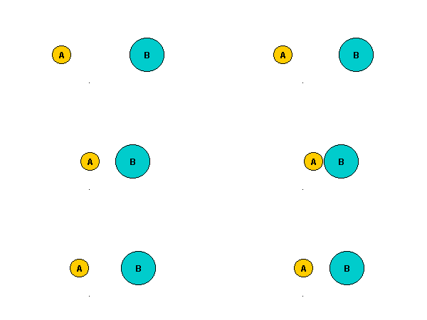
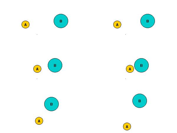
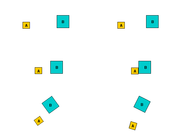
CM and impulse in same line but movement offset. Since the CM of the two objects and the impulse are in line, it seems to me that the angular momentum of the two objects wont alter? It also seems that the impulse in the x-direction is only half the above value as it only has to stop the approach velocity and the impulse in the y-direction is also half the above value as has to start the diverge velocity at this same value?

Therefore when the impulse is at 45 degrees:

impulse in x dimension = (va1- vb1)* mab  over sum

impulse in y dimension = (va1- vb1)* mab  over sum

so I wonder if we can generalise this for any angle of the impulse?

sphere

Martin

By: Nobody/Anonymous - nobody
file 2D Rotation to Linear Momentum Conversion  
2004-10-25 11:42

I'm trying to figure out how linear to rotational, and rotational to linear works. Obviously this is all about angles, and distance from the centre of mass / point of rotation. But it's not listed on the site. 
 
I've spent a while looking at it, and i've come up with the following scenarios (which are physicaly impossible, but theoreticaly sound). 
 
An object of X length, with a centre of mass exactly at one end has applied to it, a force of a non rotating collision, applied to a surface directly perpendicular to the shapes longest side. (i.e. an inverted pendulum) 
 
A linear force, acting at various points would produce a different distribution of linear to rotational energy. 
 
If the force is applied in line with the centre of mass, then the object will recieve 100% linear force, and 0% rotational. 
 
If the force is applied to the other end of the object, away from the centre of mass, at the furthest point, then the object should theoreticaly produce 100% rotation around the COM, and 0% linear. (assuming a frictionless enviroment). 
 
Therefore, a force applied half way between the centre of mass and the opposite end, should produce 50% rotational and 50% linear. 
 
 
Now, by moving the centre of mass to the middle of the object, then any force applied to either side of the COM, will have to take into account the counter weight of the other side of the object, even at the very furthest point from the COM, there will still be some linear movement generated from the collision. 
 
I'm just not sure how to get this as a calculation. 
 
Any help would be most appreciated. 
 
I was discussing this with my brothers Physics student house mates and they were also stumped. 
 
Cheers 
 
Cata 

By: Martin Baker - martinbaker
file RE: 2D Rotation to Linear Momentum Conversion  
2004-10-26 03:16

Cata, 
 
If the mass is at one end then I think what you are saying is that the moment of inertia is zero, therefore the object would have no resistance to rotation. 
 
In this case there can be no force which is not in line with the mass. From Newtons laws, every force has an equal and opposite reaction, but in this case any force would not have anything to push against so there can be no force. 
 
Martin 

By: Nobody/Anonymous - nobody
file RE: 2D Rotation to Linear Momentum Conversion  
2004-10-26 22:07

Hmmmm... ok. I understand that. 
 
But how do i calculate what percentage of a momentum is applied to rotation, and what to linear? 
 
If an object rotates around a fixed point, then it's not hard. But what about an object that can rotate and move? 
 
If it collides off the COM, then there will be some rotational, and some linear momentum. This will vary depending on friction between the two objects and the angle of collision, but a purely linear force can still produce rotational. 
 
How does this work with the reverse scenario? i.e. a rotating object colliding on a perpedicular to it's velocity. The object will clearly not rebound directly from the surface once rotation is taken into account. 
 
I've been looking for the answer for about a week now, but I still can't figure it out. 
 
Any insight you could offer would be great. 
 
Cheers 
 
Cata

By: Martin Baker - martinbaker
file RE: 2D Rotation to Linear Momentum Conversion  
2004-10-27 05:47

Cata, 
 
I find that intuition can be a bit misleading here. 
 
Forces, impulses, momentum are not split into rotational and linier parts, they apply fully to both the linier and rotational equations. I think the only quantity which is divided, part going to a linier component and part going to a rotational part is energy (which, unlike the others mentioned is a scalar quantity). 
 
If there is a net force on an object, then all of this force is used to calculate the linier acceleration using: sum of all forces=m a. If these forces are not all in line and produce a net torque then all of this torque produces an angular acceleration using T=[I]a. 
 
This may seem instinctively wrong, as if the force is being used twice but that's the way it works. 
 
Impulses work in exactly the same way. 
 
In all closed systems momentum is conserved, linier momentum is conserved and angular momentum is conserved. (total linier momentum cant be changed by converting it to angular momentum and visa versa). Angular momentum will depend on which point we calculate it about, provided we are consistent about which point we measure it about then angular momentum is always conserved. It may be that a given piece of matter is contributing to both linier and rotational momentum, but in the total closed system both quantities are conserved independently. 
 
If you would like a general equation that describes the result of a collision between two solid bodies, so would I. If you work it out please let me know. 
 
I think what you have to do is work out the impulse between the objects as we discussed in your earlier thread, you know the direction of the impulse, the difficult but is working out its magnitude. Once you know the impulse its easy, you can apply it separately and independently to the linier and rotational equations. 
 
Martin 

By: Richard - redeyes2003
file RE: 2D Rotation to Linear Momentum Conversion  
2004-10-28 18:27

Hello all, Martin, I started reasoning on this problem and so I tped out the following as a start: 
 
2D Elastic Rigid Body collision 
 
When two rigid bodies collide, it is assumed that the duration of the collision is infinitely small. Also there exists a single plane that is tangential to both bodies' surfaces at the contact point. Friction will act in this plane and the impulse of the collision will act in this plane's normal. 
It is true that Vaf,Vbf is a function result of Ma,Mb,Vai,Vbi. These notations represent initial and final velocities of two bodies A,B colliding linearly. Now it is also true that in the instance of a collision in 2d. These quantities are measurable in the plane's normal. Think of the points of contact, colliding linearly. Vai is simply the velocity of the contact point of Body A in the direction of the normal just upon collision. (Any other motion constitutes friction in the plane.) Ma is the inertial mass that a force will see acting at this point in the normal direction.* Thus Vaf is found. This is an indirect method and requires simplification. 
Vaf - Vai is the change in velocity. And there is a ratio** for how much goes into translation and rotation. Consider the force acting on the body at that point, there will be linear and angular acceleration. Likewise, there is linear and angular change in velocities. 
 
*Ma=1/((1/M)+(r.r/I)) 
*Va=working on it, the display format is complex for decribing current rotation 
**Ratio is linear to rotational velocities; rotational vel is not angular vel, but the velocity of the contact point due to the rotation. 
 

By: Nobody/Anonymous - nobody
file RE: 2D Rotation to Linear Momentum Conversion  
2004-10-30 14:19

Well, if you look at a simple, long thin object of 10x1 units with a centre of mass in the middle (5,0.5), then a collision at any point off the centre of mass will produce a rotational and linear movement. I.e. (7.5,0). 
 
It's impossible that this object would either move without rotating, or rotate without moving. Therefore, there has to be some relationship between distance from COM and energy transfered into linear /rotational momentum. 
 
At the COM (5,0) from a velocity of (0,2), the linear momentum would be 100% transfered with no rotation. 


=========== 

 
But a collision at the very edge of the object, the furthest point from the COM, (10,0) from a velocity of (0,2) would have to produce some rotational momentum. 


=========== 


Think of this as the effect of a pool ball. If it is struck dead centre then it will move forward with no rotation around the vertical axis. But if it is struck on the very edge of the ball, it does not move linearly, but will instead almost rotate in place. These are both linear, non rotational collisions that produce wildly different effects. 
 
This is also tied to the angle at which the collision occurs. So a collision ocurring perpendicular will transfer 100% of the energy into the collision, as opposed to a collision that occurs "parallel" i.e. a slight brush, which will transfer <1% of the collision. 
 
I will play around with these equations and see if I can get them working. The theory feels right, but i'm unsure how to implement it. 
 
Cata

By: Richard - redeyes2003
file RE: 2D Rotation to Linear Momentum Conversion  
2004-10-31 15:59

Hi Carta, 
 
The simpliest variables to consider in your problem are mass and velocity. There are two masses: the mass of the long, thin object and the mass of the object that hits it. There are two velocities: and thes are the velocities of these 2 objects. 
 
These variables here are governed by the conservation rule of energy and momentum. 
 
Consider a heavy particle hitting the long object at its end. It will rotate. If a lighter particle hit the long object at its end in a similar way as the heavy particle. The long object will rotate less than before. Now it the same heavy particle hit the long object with more speed than before, then the long objct will rotate more quickly. It can be noticed, therefore, that the mass and velocity affect the outcome. 
 
The reason for this is base on Newtons law of F=Ma. On collision, there is an impulse between both objects, where a force acts on both objects until they separate. Based on F=Ma, the greater the mass the slower it will move away in the collision. (Rotational inertia behaves in the same way) And the greater the collision velocities(approaching velocity) the the greater the impuse felt on collision. 
 
Anyways, there are equations derived that state the separting velocities when the collision velocities are known and the masses of the objects are known. 
https://www.euclideanspace.com/physics/dynamics/collision/index.htm 
This is for linear collision. 
 
For 2d collision, it gets more complicated but the linear collison still holds true, IMO. For, at the instance and duration of the collision, there are 'velocities' and 'masses' colliding linearly. Still, this is just my perspective. (Not the actual velocities and masses of the objects, though) 
 
For your problem, you would need to consider the rotational inertia just as how we looked at the mass of the object. 
 
... 
Richard

By: Richard - redeyes2003
file RE: 2D Rotation to Linear Momentum Conversion  
2004-11-12 10:35

OK, I am working this out 1 dimension at a time but ultimately in 3d. 
 
I am trying to figure out the approaching velocity when the rotation and translation are taken together. The approaching velocity just before contact of the colliding surfaces. 
 
I have already worked the rest of the problem and just want the solution in simple terms 
 
So far I am investigating what veocities are present in the normal of the colliding surfaces. 
And I am trying to represent angular velocity about the priciple axes of both objects

By: Richard - redeyes2003
file RE: 2D Rotation to Linear Momentum Conversion  
2004-11-12 10:41

con't 
 
It is assumed the contact point is given as a vector from objects center to the surface and is in the frame of the principle axes 
 
I am pondering...

By: Richard - redeyes2003
file RE: 2D Rotation to Linear Momentum Conversion  
2004-11-12 11:17

con't 
The radii are known, ie the radius of the line of action of the impulse about each principle axes

By: Richard - redeyes2003
file RE: 2D Rotation to Linear Momentum Conversion  
2004-12-16 01:39

Started thinking about the problem again and found a little breal tru. Think I might actually have the solution by next year. 
 
I will use an impulse equation in 3d on an object. This gives the change in velocity & angular velocity for any given impulse. 
 
Does anyone know if it is correct to say that 
S crossproduct R is Angular momentum vector? 
where S is impulse and R is the positional vector of the contact point all given in Local frame 

By: Martin Baker - martinbaker
file RE: 2D Rotation to Linear Momentum Conversion  
2004-12-16 11:18

Some thoughts: 
I have usually seen the relationship between torque and force written as: 
T = sum(r x F) 
So if we integrate both sides with respect to time. 
dT = sum(r x dF) 
where dF is impulse and dT is a torque equivalent of impulse. 
 
(I'm never sure if the order of (r x F) is dependant on whether we are using a left handed or right hang coordinate system?) 
 
In the linier case we have: 
F = m a 
Integrate both sides we get 
Impulse = dF = m da = change in momentum 
 
In the rotational case we have: 
T = [I]a 
So integrating both sides do we get: 
dT = [I] da 
I think this might not be valid because [I] can be a function of time? 
 
Martin 

By: Richard - redeyes2003
file RE: 2D Rotation to Linear Momentum Conversion  
2004-12-17 22:46

OK I followed u up to dT = [I] da 
 
The crossproduct of Impulse and R gives change in angular momentum [Wrong] 
 
Actually I found this is not entirely correct. It gives the direction of the angular momentum but not the magnitude of the change. 
 
How this was derived: 
Consider any frame, there is a force acting in that frame. Let the components of that force act solely in each direction of the frames axes. Now each component can cause a rotation about the other two axes simultaneously. 
 
Now basic angular velocity, w, is given by 
a = F.r / I 
w = Fdt.r / I 
w = S.r / I 
 
Consider the z component of the force(Impulse S) causing the rotations about the y and x axes respectively 
Wy = Sz * Rx / Iy 
Wx = -Sz * Ry / Ix 
(You might have to draw the y and x axes on paper in 2D then draw a point anywhere representing the z component of S into or out of the paper) The coordinates of the point is always Rx,Ry 
 
Take a convention: w is clockwise in the direction of axis, x is right, y is up, and z is into the paper. You will see that when Wy is positive when Sz * Rx is positive and so on gives, 
 
Rotations caused by x component of Impuse 
Wz = Sx * Ry / Iz 
Wy = -Sx * Rz / Iy 
 
Rotations caused by y component of Impuse 
Wx = Sy * Rz / Ix 
Wz = -Sy * Rx / Iz 
 
 
Adding all the rotation about comman axes gives: 
Wx * Ix = Sy * Rz - Sz * Ry 
 
Wy * Iy = Sz * Rx - Sx * Rz 
 
Wz * Iz = Sx * Ry - Sy * Rx 
 
This result resembles a crossproduct. However, an error was made somewhere. I think I should have worked with the Force F and then intergrate with dt to get Impulse S in the final result 

By: Martin Baker - martinbaker
file RE: 2D Rotation to Linear Momentum Conversion  
2004-12-19 00:42

Don't forget that [I] is inertia tensor matrix so we cant divide by matrix (although we can multiply by inverse of matrix) and we cant treat it like a constant in the equations. 
 
Martin 

By: Richard - redeyes2003
file RE: 2D Rotation to Linear Momentum Conversion  
2004-12-19 14:12

The (Ix, Iy, and Iz) that were used, were positive scalars. They are the interias about each axis of the frame that is under consideration. For simplicity, I used the frame when the [I] is diagonalized, ie the frame in which Ix is the same as the tensor 
[Ix,0,0, 
0,Iy,0, 
0,0,Iz] 
 
I think the correction to the problem is 
dWx * Ix = (dFy * Rz - dFz * Ry)dt 
dWy * Iy = (dFz * Rx - dFx * Rz)dt 
dWz * Iz = (dFx * Ry - dFy * Rx)dt 
 
using force instead of impulse, and integrating dF

By: Richard - redeyes2003
file RE: 2D Rotation to Linear Momentum Conversion  
2004-12-19 14:18

I am attempting a minor detour, I think

By: Richard - redeyes2003
file RE: 2D Rotation to Linear Momentum Conversion  
2004-12-20 12:16

Ahaaa progress... 
 
I revisted the original idea of this post and found that it was right on track. It was flawed but best one so far. 
 
When a force acts on an object, the only thing that governs the amount of linear and translation that it recieves is the distance force line from cente of object. Intuitively. Both motions are dependent on some function of distance. This function is not linear. 
 
Consider any 2d object to be 
--------(0.5M)----------------(0.5M)-------- 
 
The object that is splitted into two halves, and the center of mass (0.5M) is considered for both halves. Call the distance of separation of these 2 sub-centers to be D. Then let a force be applied anywhere on this object, at a distance of nD, where n is any factor. It is intuitive that the amount of translation and rotation is some Function(n) if you appreciate that the M variable is a not contributing factor (by simple scaling the applied force) and D is always D, ie constant

By: Richard - redeyes2003
file RE: 2D Rotation to Linear Momentum Conversion  
2004-12-24 04:24

I = Mrr = M.1/2D.1/2D 
I/M = 1/2D.1/2D 
Sqrt(I/M) = sqrt(1/2D.1/2D) 
Sqrt(I/M) = 1/2D 
D=2. Sqrt(I/M) 
 
I figure that when a force acts on the object causing it to translate and rotate, it eperience a total momentum change equal to the impulse it recieved, and both translate and rotate accelerations (or velocity change) are propotionate to the force. Trying something again...

By: Richard - redeyes2003
file RE: 2D Rotation to Linear Momentum Conversion  
2004-12-25 22:52

By using this method of equating the rotational inertia with that of a point mass at a distance D/2, then 
 
Linear Acceleration: F/m 
 
Rotational Acceleration: Fr/I 
(r is the distance from center to the impulse) 
This is produced from the torque on the object, and if we consider it to be 2 point masses rotating, we derive the next step) 
Linear semi-Center Acc: (Fr/I)*(D/2) 
(D is the distance between semi-Centers) 


Linear Rate of momentum change(thus is the normal center): 
= mA = F 
Linear Rate of momentum change for semi-Centers: 
= m*(Fr/I)*(D/2)= m*(Fr/I)*(sqrt(I/m))= F*(mr/I)*(sqrt(I/m)) 


^^^Total Rate of momentum change = F + F*(mr/I)*(sqrt(I/m)) 
^^^For a finite impulse or momentum change, the relative rates at which the momentum change in both styles given are proportional to the amount of impulse each will convert 
 
 
Linear Momentum change for impulse Jlin 
= F/( F + F*(mr/I)*(sqrt(I/m))) J 
= 1/( 1 + (mr/I)*(sqrt(I/m))) J 
Momentum change for semi center = 
= F*(mr/I)*(sqrt(I/m))/( F + F*(mr/I)*(sqrt(I/m))) J 
= (mr/I)*(sqrt(I/m))/( 1 + (mr/I)*(sqrt(I/m))) J 


The ratio of momentum that contributes to linear and rotational are: 
 
Linear momentum change for impulse J = J * 1 / (1 + (mr/I)*sqrt(I/m)) 
 
Momentum change for impulse J that goes into rotation(not equal to the angular momentum) 
= J * (mr/I)*sqrt(I/m) / (1 + (mr/I)*sqrt(I/m)) 
 
Therefore the change in linear and angular velocities are: 
(divide by m) 
 
Delta v = J * (1/(m + (m*m*r/I)*sqrt(I/m))) 
 
(divide by m to get linear velocity and then divide by sqrt(I/m) to get angular velocity) 
Delta w = J * (r / (I + m*r*sqrt(I/m))) 

By: Richard - redeyes2003
file RE: 2D Rotation to Linear Momentum Conversion  
2004-12-28 02:12

Simplified 
 
change in linear velocity is:  
 
Delta v = (J/m) * 1/(1 + r/R)  
 
where r is distance from center of mass to the impulse and R=sqrt(I/m)=constant 
 
change in angular velocity is: 
 
Delta w = (J*r/I) * 1/(1 + r/R) 
 
I checked this result with a previous result that I did and the previous one was incorrect 
 
I am thinking of applying this to 3d, say an impulse in the x direction translate an object in the x direction and rotates it about the y and z axes. Problem is, an impulse in the y direction also affects rotation on the z axis and its effect may be negative rotation to the one caused by the x impulse. Taking the x or y direction of the impulse alone is fine. Finding the combined rate of momentum change is more difficult.


metadata block
see also:
Correspondence about this page

Book Shop - Further reading.

Where I can, I have put links to Amazon for books that are relevant to the subject, click on the appropriate country flag to get more details of the book or to buy it from them.

cover Robot Dynamics Algorithms (Kluwer International Series in Engineering and Computer Science, 22)

Commercial Software Shop

Where I can, I have put links to Amazon for commercial software, not directly related to the software project, but related to the subject being discussed, click on the appropriate country flag to get more details of the software or to buy it from them.


This site may have errors. Don't use for critical systems.

Copyright (c) 1998-2023 Martin John Baker - All rights reserved - privacy policy.