This page contains information about mesh reduction and mesh repair, etc.
The first part of this page is a discussion of the principles of mesh reduction, this second part of this page has information about a much more efficient method by Michael Garland and Paul Heckbert (Surface simplification using quadric error metrics).
Mesh Reduction
This is about algorithms to reduce the amount of data needed to represent the mesh while minimising any distortion to the mesh this would cause. For example, if we have the following mesh:
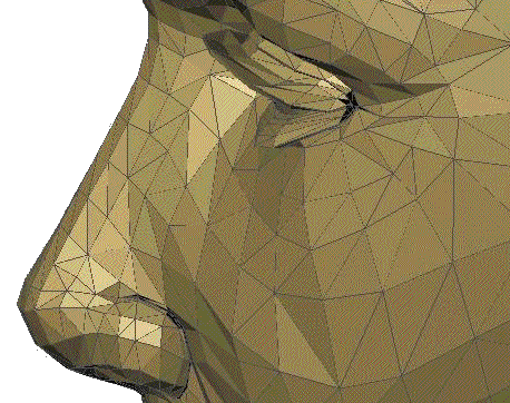
We want to reduce the number of polygons required to make this model while minimising the distortion that this will cause. To do this we can try removing each polygon in turn and measure the distortion caused, for example we might try removing vertex 1.
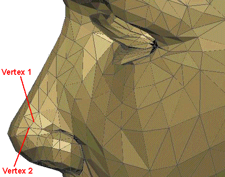
To remove vertex 1 we merge it with vertex 2, to do this we can slide it along the edge that joins them, as follows:
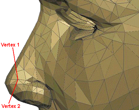
In this case the result is to replace 4 triangles by a single 4 sided polygon, although this will differ depending on which vertices are moved. If we want to work with triangles only we could replace the 4 sided polygon with 2 triangles, this would also ensure that all points on the polygons are in the same plane.
A possibly better alternative is to merge vertex 1 and vertex 2 by moving them both to a new common vertex at their midpoint:
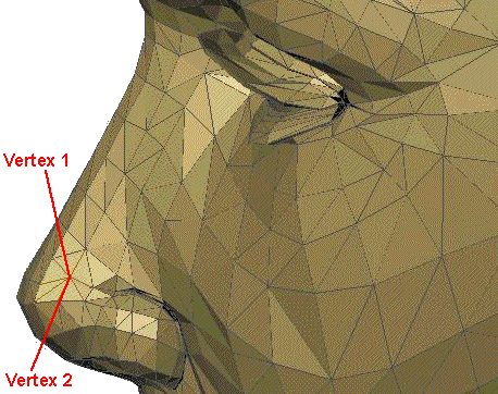
This has replaced 9 triangles with 7 triangles. So in both cases we have reduced the number of triangles by 2, but in the second case the triangles are likely to be more equal in size, so the average error may be less.
So, how much distortion has this caused? In other words, what is the average difference between the original position of vertex 1 and the nearest point on the mesh? To do this here is a diagram looking along the plane of the surface:
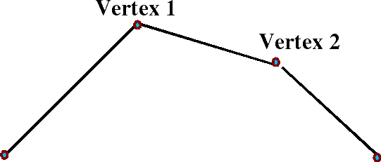
When we replace vertex 1 and vertex 2 with the blue point below:
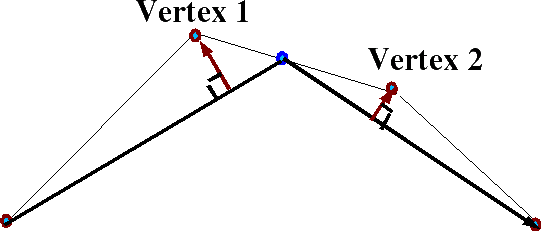
The red arrows then can be used as a measure of the error caused by the simplification.
So if we show each of these error distances separately as follows:
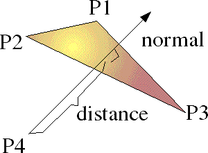
Where:
- P1, P2 and P3 are 3 vertices of the polygon which define the plane.
- P4 is the original position of a point which is now being moved to the plane.
- normal is a normal vector to the plane
- distance is the shortest distance that P4 has to move to be on the plane.
As described here the normal to the polygon can be calculated from the cross product of any two sides of the polygon, so,
normal = | (P1 - P3) x (P2 - P3) |
so expanding out the cross product gives:
Nx = (P1y - P3y)(P2z - P3z) - (P2y - P3y)(P1z - P3z)
Ny = (P1z - P3z)(P2x - P3x) - (P2z - P3z)(P1x - P3x)
Nz = (P1x - P3x)(P2y - P3y) - (P2x - P3x)(P1y - P3y)
so multiplying out the terms gives:
Nx = P1y*P2z -P1y*P3z- P3y*P2z + P3y*P3z - P2y*P1z +P2y*P3z +P3y*P1z - P3y*P3z
Ny = P1z*P2x -P1z*P3x- P3z*P2x + P3z*P3x - P2z*P1x +P2z*P3x +P3z*P1x - P3z*P3x
Nz = P1x*P2y -P1x*P3y- P3x*P2y + P3x*P3y - P2x*P1y +P2x*P3y +P3x*P1y - P3x*P3y
cancelling out terms gives:
Nx = P1y*P2z -P1y*P3z- P3y*P2z - P2y*P1z +P2y*P3z +P3y*P1z
Ny = P1z*P2x -P1z*P3x- P3z*P2x - P2z*P1x +P2z*P3x +P3z*P1x
Nz = P1x*P2y -P1x*P3y- P3x*P2y - P2x*P1y +P2x*P3y +P3x*P1y
What we want to find is the perpendicular distance from P4 to the plane. This is equivalent to the distance from P4 to any point on the plane (say P3) projected onto the normal.
Vector A projected onto vector B is given by:
A || B = A•B * B/|B|2
as explained here.
So the distance from P4 to P3 projected onto the normal is given by:
(P3-P4) || N = (P3-P4)•N * N/|N|2
= (P1y*P2z -P1y*P3z- P3y*P2z - P2y*P1z +P2y*P3z +P3y*P1z) * (P3x - P4x)
+ ( P1z*P2x -P1z*P3x- P3z*P2x - P2z*P1x +P2z*P3x +P3z*P1x) * (P3y - P4y)
+ ( P1x*P2y -P1x*P3y- P3x*P2y - P2x*P1y +P2x*P3y +P3x*P1y) * (P3z - P4z)
divided by | N | = sqrt (Nx2 + Ny2 + Nz2)
|
Alternative method If we define the plane as follows A x + B y + C z + D = 0
(A P4x + B P4y + C P4z + D) / sqrt(A2 + B2 + C2) |
Recalculation of normals, texture coordinates and colours.
We must remember to recalculate these parameters associated with the vertex. If we average the position of two points I imagine that we can average their associated normals, texture coordinates and colours. Although in the case of normals it may be more efficient to discard them and recalculate them at the end of the algorithm as described here.
Algorithm
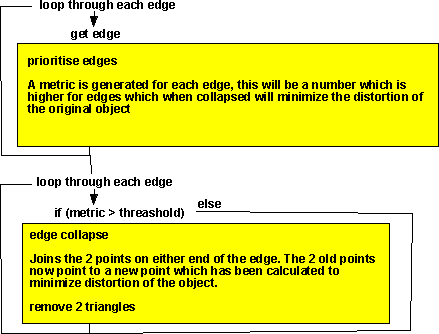
This is based on the message here.
The equations above are quite complex which would make the algorithm very slow and I suspect it would not be very resilient (for example if a face has 3 vertices in a line).
I suspect that, instead of working out the error from the vertex position removed and the 3 vertices at the corners of a triangular section of plane, it might be simpler to take these 4 points and calculate the minimum curvature of a plane to make it pass through all 4 points? I've no idea how to work this out, can anyone help me?
Surface simplification using quadric error metrics
This describes a much more efficient method by Michael Garland and Paul Heckbert (Surface simplification using quadric error metrics). For a full description see Garlands paper.
This method involves calculating a 4x4 matrix [Q] for every vertex in the mesh, the terms in the matrix are as follows:
| a*a | a*b | a*c | a*d |
| b*a | b*b | b*c | b*d |
| c*a | c*b | c*c | c*d |
| d*a | d*b | d*c | d*d |
- a = n.x
- b = n.y
- c = n.z
- d = -(p dot n)
- p = position vector of this vertex.
- n = unit normal at the vertex.
When we are working on a mesh represented by an indexed face set, we usually have arrays containing the position and normal of each vertex, so it is relativly easy to calculate [Q] for every vertex.
When we try collapsing an edge we can work out the error metric by the sum of every: vt [Q] v
where:
- v = [p.x p.y p.z 1.0] i.e. p (position of vertex) padded out with an extra 1.
- vt = the transpose of v vector, i.e. the vector as a row rather than a column.
So the term vt [Q] v is a single scalar value, as the sum of these values gives the total error metric for the surface. If we calculate this error metric before collapsing any edges, the we must get zero, i.e. no error. I have proved this here.
Then when we collapse an edge we just add together the corresponding [Q] for each vertex to give [Q] for the new vertex.
For example, if vertex v1 and vertex v2 are collapsed to vertex v3 and [Q1] is the Q matrix at v1 and [Q2] is the Q matrix at v2, then the error metric is given by:
v3t [Q1 + Q2] v3
So we can search through all the possible edge collapses looking for those that give the least error metric.
After we have collapsed an edge, we replace the vertexes with the new vertex, update the error metric of any vertex connected to the new vertex, we can now collapse the next edge until we have simplified the mesh enough.
